Introduzione

Use this guide to remove or replace the rear camera module on your Samsung Galaxy Note10+.

  1. fL4GhRIqG5WekoPm
    fL4GhRIqG5WekoPm
    mNlPIu46FeCRPTb3
    KYcY2L3Mlotv3mAh
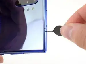
    • Insert a SIM eject tool, bit, or a straightened paper clip into the small hole on the SIM card tray on the top edge of the phone.

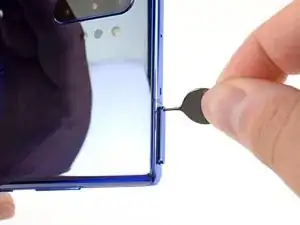
    • Press firmly to eject the tray.

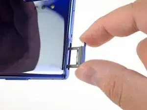
    • Remove the SIM card tray.

  2. ml6MyNw6cSOJYfQ6
    • Completely power off your phone before you begin disassembly.

    • Prepare an iOpener and apply it to the left edge of the rear cover for one minute.

    • A hair dryer, heat gun, or hot plate may also be used, but be careful not to overheat the phone—the display and internal battery are both susceptible to heat damage.

    I have an adjustable hot plate. I bought it when I replaced the back and battery on a previous note. I am wondering about some type of shim so that the camera bump is not in contact with the hot plate. I am thinking about fender washers. Is there a better way?

    Rusty Lingenfelter -

  3. HX3lmgWJZxP6gr5L
    HX3lmgWJZxP6gr5L
    cFfqjRPLFsNjCQh5
    hsHDVSxhDmoElZ1D
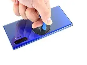
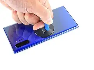
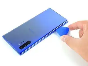
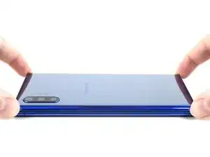
    • Apply a suction cup to the heated edge of the rear cover, as close to the edge as possible.

    • If your rear cover is badly cracked, covering it with a layer of clear packing tape may allow the suction cup to adhere. Alternatively, very strong tape may be used instead of the suction cup. If all else fails, you can superglue the suction cup to the broken cover.

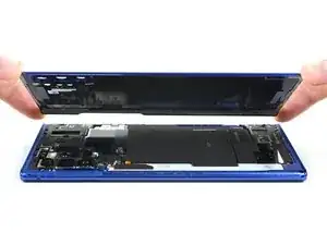
    • Pull up on the suction cup with strong, steady force to create a gap between the rear cover and the frame.

    • Depending on the age of your phone, this may be difficult. If you are having trouble, apply more heat to the edge and try again.

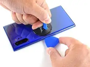
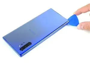
    • Insert the point of an opening pick into the gap.

  4. FefebrYwhOSr1QIk
    FefebrYwhOSr1QIk
    VZSJVpUOEW2t6YaG
    MxKEHaMiepqgTNmw
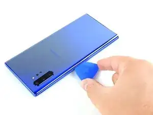
    • Slide the opening pick along the left edge towards the bottom left corner to slice the adhesive.

    • Don't insert the opening pick more than halfway into the phone or you risk damaging internal components.

    • Leave the pick inserted in the bottom left corner to prevent the adhesive from re-sealing.

  5. QoQcvfF4MNCs14jm
    QoQcvfF4MNCs14jm
    NQZtJHs3MHygk2Eb
    Ca6XWHfrwr5uw5Ad
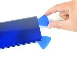
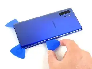
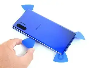
    • Repeat the previous heating and cutting procedure for the remaining three sides of the phone.

    • Leave an opening pick on each side as you continue to the next to prevent the adhesive from resealing.

    • The rear cover will begin to separate from the phone as you finish all sides of the phone.

    Be extremely carefull: rear cover is very fragile!

    Elbert Ainstein -

  6. gawK5DKp5YOpPqde
    gawK5DKp5YOpPqde
    DFTaEKoPEDBeRhtw
    • Lift the rear cover straight up to remove it.

    • Follow this guide to reinstall the rear cover and replace the adhesive.

    • Be sure to turn on your device and test your repair before installing new adhesive and resealing the device.

    • If you're using Tesa tape to reattach components, follow this guide.

    Muy buena la guia. nada que añadir. para montar solo limpia el equipo donde estaba el tape anterior, y remoueve los el tape de la tapa nueva solo ponla y listo…

    Manuel carrion -

  7. 2FbQ23b6dCmXnmwZ
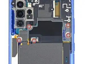
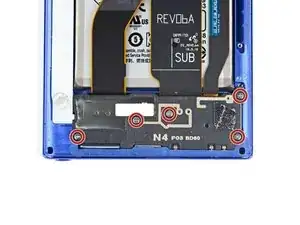
    • Use a Phillips screwdriver to remove the five 4 mm screws securing the wireless charging coil.

    Phillips #000

    fosgate3 -

  8. xq2NcNvraJy5sUFG
    xq2NcNvraJy5sUFG
    flf1lIYvkvDDbRFq
    grviB2BXFe5bDtTG
    • Use a pair of tweezers to lift up and flip back the metal shield covering the battery connector.

  9. 5UvMajJaDmgaQUio
    5UvMajJaDmgaQUio
    w4ulAlWkFmOYWY6y
    • While holding the metal shield up and out of the way, use the pointed end of a spudger to pry up the battery connector to disconnect it.

  10. Fd2BpNmvBVegJYfI
    Fd2BpNmvBVegJYfI
    mZCVdoImRIl2hJLP
    • Use the pointed end of a spudger to disconnect the wireless charging coil connector from the motherboard.

  11. D6GBUnOKGIEDXQCH
    D6GBUnOKGIEDXQCH
    xX3biuVC1ilwDRMI
    bAB5bBQr5dtWu51B
    • Tilt the metal shielding up so you can grip it with your fingers.

    • Peel the wireless charging coil up and away from the device.

    • The wireless charging coil is secured to the phone with some light adhesive.

    • Remove the wireless charging coil.

    Can you reuse the wireless charging coil? I don’t see a replacement on the site. I just learning all this.

    Jon Marble -

  12. dUYnVngZYbvynIjf
    • Use a Phillips screwdriver to remove the five 4 mm screws securing the loudspeaker.

  13. jWhyREpcKXubPZmi
    jWhyREpcKXubPZmi
    AIPgsnn2XKZQVYlZ
    JwKFcNyahIYynQoU
    • Use a pair of tweezers to remove the loudspeaker.

  14. ccwP12q1is1rbReW
    ccwP12q1is1rbReW
    hYRmIXQlbywga5mF
    NxLcYggtAeG3MH1d
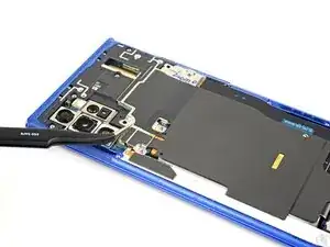
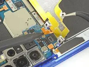
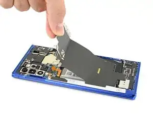
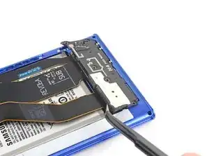
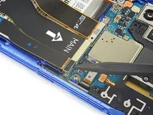
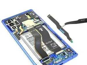
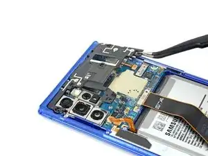
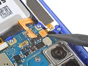
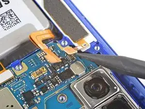
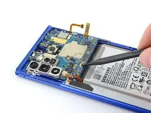
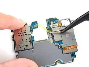
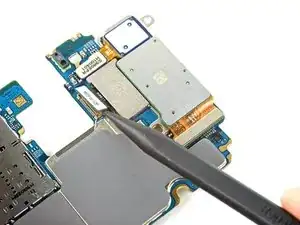
    • Use the pointed end of a spudger to disconnect the main interconnect cable from the motherboard.

    • Disconnect the secondary interconnect cable from the motherboard.

  15. MpqxWloMh1SXrO1o
    MpqxWloMh1SXrO1o
    DMUOYb2KLVu3uCsx
    iB3NlojpWm6SWUdo
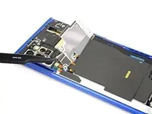
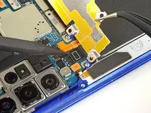
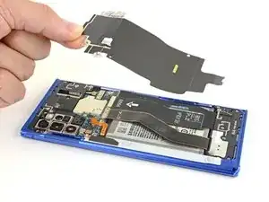
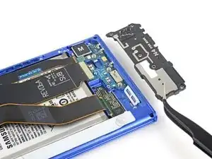
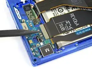
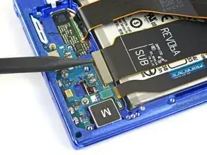
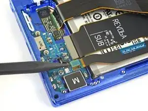
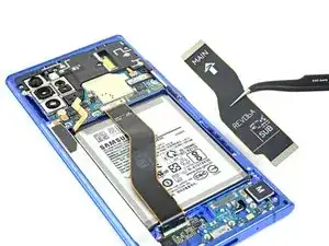
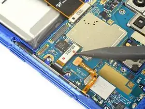
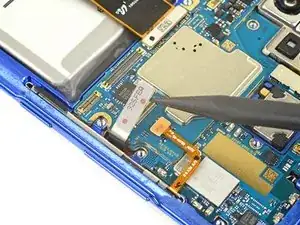
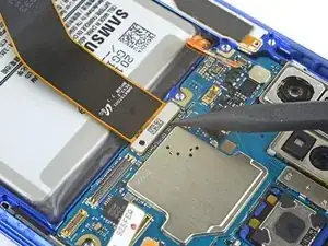
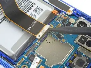
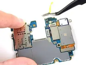
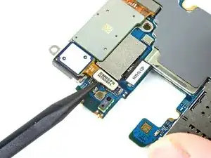
    • Use the pointed end of a spudger to disconnect the main interconnect cable from the daughterboard.

    • Disconnect the secondary interconnect cable from the daughterboard.

  16. ggdArbZZmhi1By3A
    ggdArbZZmhi1By3A
    aN6yxVRL4VhXiCVL
    • Remove both interconnect cables.

  17. B6iWFNNIGD4XIMnC
    • Use a Phillips screwdriver to remove the four 4 mm screws securing the top plastic cover.

  18. wBshCpmX4uf4XILP
    wBshCpmX4uf4XILP
    dEYRmAKfQRXjBmFk
    FxAS2yGCcJ5eP21V
    • Use a pair of tweezers to pivot the top plastic cover up and off of the phone.

  19. LoHtEGCHkRGYw3LJ
    LoHtEGCHkRGYw3LJ
    Bfa6fUKEhsTdRMHo
    J2aqFMYLRi6KjUEr
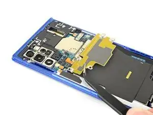
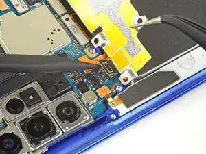
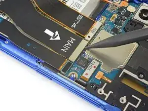
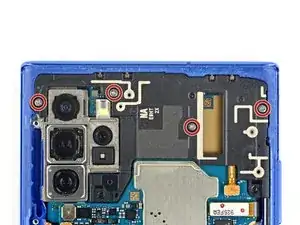
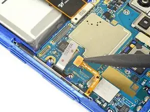
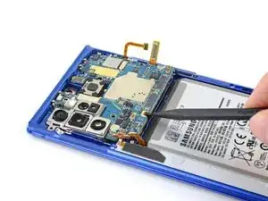
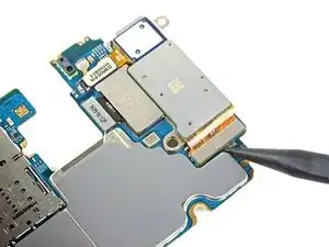
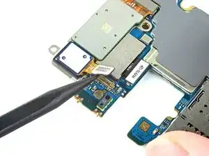
    • Use the pointed end of a spudger to disconnect the touch layer connector from the motherboard.

    • Disconnect the side button connector from the motherboard.

  20. 1LQqJWkjeBsHrAmu
    1LQqJWkjeBsHrAmu
    YSKZ6SOxdqkDXY6S
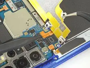
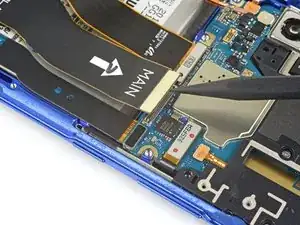
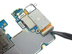
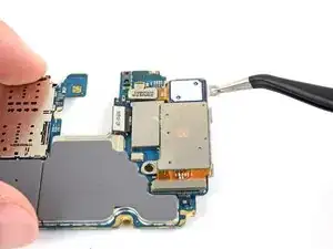
    • Use the pointed end of a spudger to disconnect the S-Pen charging coil connector from the motherboard.

  21. 4Zj2VdkHcSmRV3TJ
    4Zj2VdkHcSmRV3TJ
    jd2wNCLNgP5G5HiZ
    • Use the pointed end of a spudger to disconnect the display cable from the motherboard.

  22. B2EMfXeYbK6CIPMJ
    B2EMfXeYbK6CIPMJ
    afRHFdTepBPMbTRL
    Du3ZOw1ZBUF5XbAo
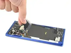
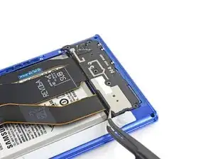
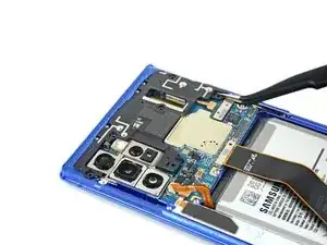
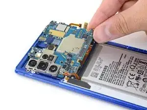
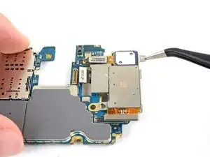
    • Use the pointed end of a spudger to pry up the motherboard enough to grip it with your fingers.

    • Remove the motherboard.

  23. D2eJ1kjlcPELTyLU
    D2eJ1kjlcPELTyLU
    hGBFr2fBPZECKRGT
    NNuVhUH4eFkkE1N3
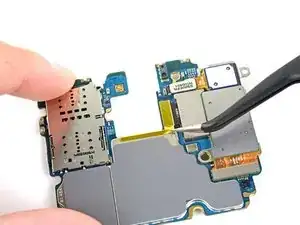
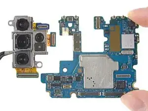
    • Use a pair of tweezers to remove the small piece of tape covering the middle camera connector.

    There were two tapes in my phone, instead the one of “L”shape, so it wasn’t nesessary to remove them.

    Elbert Ainstein -

  24. 6C6LPWAEoIjMOyUO
    6C6LPWAEoIjMOyUO
    PnLCXXpcYpZTFWOC
    KkAvEACpg2TtRplK
    • Use the pointed end of a spudger to disconnect the bottom camera connector.

    • Disconnect the middle camera connector.

  25. 2bprgf1qsTCxF6MX
    2bprgf1qsTCxF6MX
    cEispHk2AS2UoAI4
    • Use the pointed end of a spudger to disconnect the top camera connector.

  26. pvJ3iymFhdNWgHOf
    pvJ3iymFhdNWgHOf
    DLMabBIpwL1QuyUb
    YFqNeUWVhBTRTea4
    • Use a pair of tweezers or your fingers to remove the rear camera module.

    A new camera module came with a protective cover, so don’t forget to remove it before installation.

    Elbert Ainstein -

Conclusione

Compare your new replacement part to the original part—you may need to transfer remaining components or remove adhesive backings from the new part before installing.

To reassemble your device, follow the above steps in reverse order.

Take your e-waste to an R2 or e-Stewards certified recycler.

Repair didn’t go as planned? Try some basic troubleshooting, or ask our Answers community for help.

Carsten Frauenheim

Membro da: 10/03/20

110750 Reputazione

0 commenti