Introduzione
This guide will show you how to replace and repair both Front and Rear cameras on the device.
Strumenti
-
-
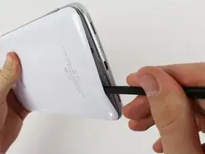
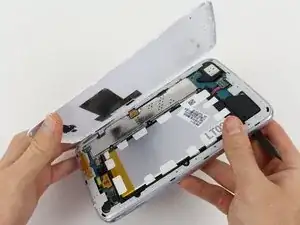
To begin working on your repair, turn your device over and open the micro SD slot, as shown in the first picture.
-
Using the flat part of the spudger, begin pushing it between the white backing and the SD slot. Continue to pry off the white backing until you hear several clicks and see the white backing lift up, as shown in the second picture.
-
Continue to pry off the white backing around the device, as shown in the third picture.
-
-
-
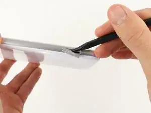
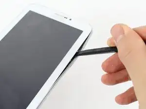
To remove the silver siding, begin by pushing the spudger between the frame and the screen, as shown in the first picture.
-
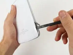
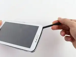
Do this until you see the silver siding begin to lift up. Continue doing this around the edges of the device, as shown in the second picture.
-
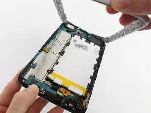
Once you silver siding is loose all around the device, remove it carefully with your hand as shown in the third picture.
-
-
-
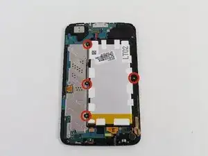
Begin by removing the four designated 1.33x2.00 mm Phillips screws with the screwdriver, as shown in the first picture.
-
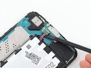
Once the screws are removed, use a pair of tweezers or the spudger to remove the battery connector.
-
Pull the battery connector up as shown in the second picture.
-
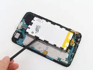
Once the battery connector is removed, you can remove the battery using the spudger as shown in the third picture.
-
-
-
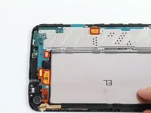
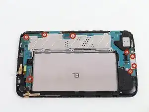
To begin replacing mother board, remove the six flat-topped connectors shown in the first picture.
-
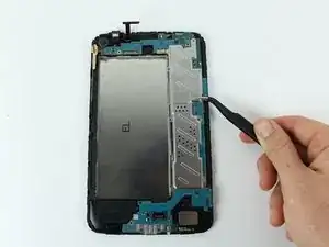
Remove the connections by pulling them up carefully using a spudger or tweezers, as shown in the second picture.
-
-
-
First, Remove eight 1.33x2.00mm Phillip screws.
-
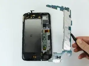
Once all the screws are removed, remove the motherboard using the tweezers.
-
Once the motherboard is removed, your device should look like the device in the third picture.
-
-
-
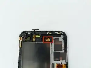
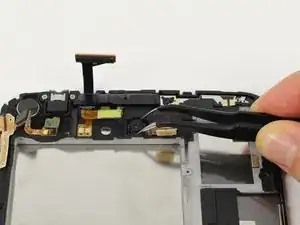
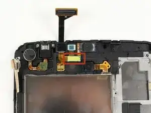
Using tweezers or the spudger, remove the flat-topped connector that is shown in the first picture.
-
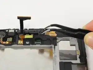
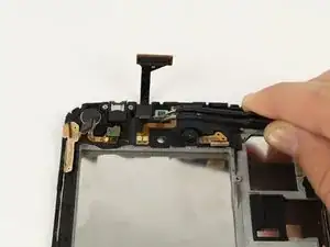
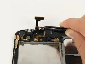
Once the connector is detached, remove the rear camera using tweezers, as shown in the second and third pictures.
-
-
-
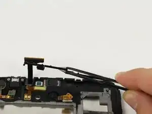
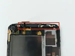
Begin removing the front camera by popping off the plastic stopper shown in the first picture.
-
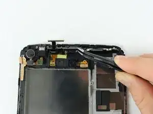
Remove the plastic stopper with tweezers as shown in the second picture
-
-
-
Once the plastic stopper is removed, use tweezers to remove the flat-topped connector for the front camera.
-
Once the connection is unconnected, remove both the connector and the camera.
-

To reassemble your device, follow these instructions in reverse order.