Introduzione
If your camera has been exposed to high heat or prolonged periods of time in high temperature conditions, your camera's image sensor could be shot. A bad image sensor can cause a very distorted image or in some cases even a completely black screen when turned on.
-
-
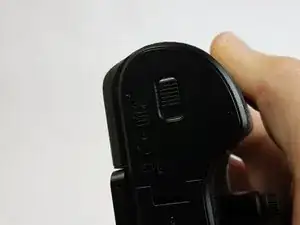
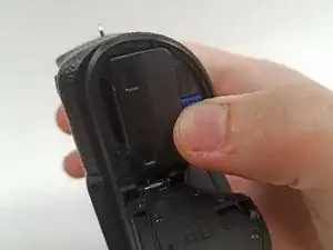
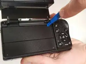
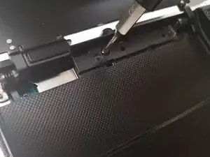
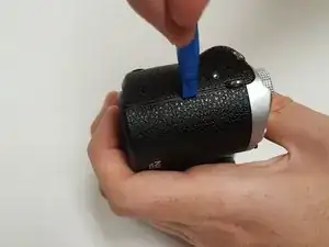
Open the screen exposing the hinge cover and place the plastic opening tool inside.
-
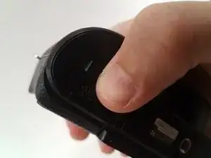
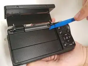
Pry the hinge cover up by moving the plastic opening tool in a downward motion.
-
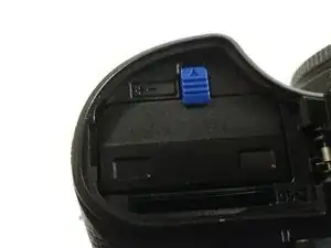
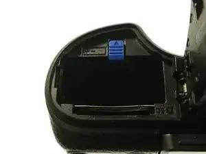
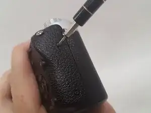
Remove the black 4mm Phillips #000 screw that is revealed once the hinge cover is removed.
-
-
-
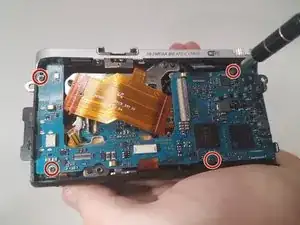
Unscrew the two 4 mm Phillips #000 screws on the right hand side of the camera using the screwdriver.
-
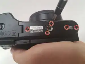
Unscrew five more 4 mm Phillips #000 screws that are located at the bottom of the camera with the screwdriver.
-
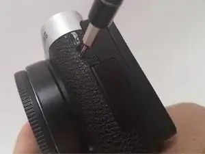
Remove the last exterior 4 mm Phillips #000 screws on the left hand side of the camera with the scredriver.
-
-
-
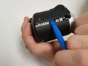
Use the plastic opening tool in a downward motion around each side of the camera to pry the casing open.
-
-
-
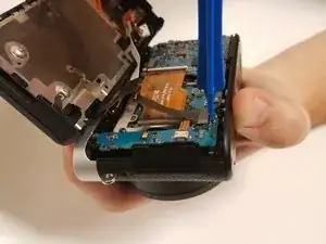
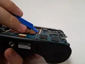
Locate the black ribbon at the bottom left of the camera's interior.
-
Place the plastic opening tool under the black ribbon connector.
-
Remove the cable by moving your plastic opening tool in a downward motion.
-
-
-
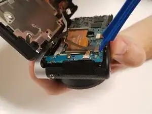
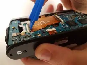
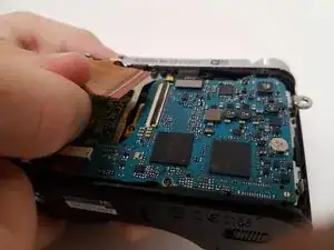
Lift the black latch of the left main ribbon connector using a wide-set plastic opening tool in a downward motion.
-
Use your fingers to disconnect the cable.
-
-
-
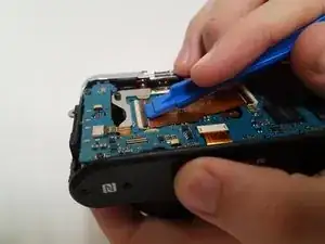
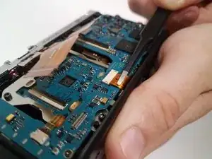
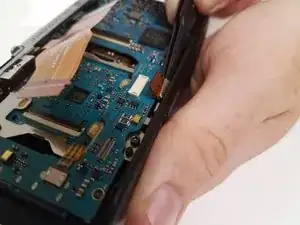
Use the wide-set plastic opening tool to lift the latch on the right main ZIF cable in a downward motion.
-
Disconnect the cable using your finger.
-
-
-
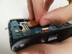
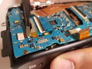
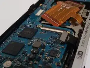
Locate the ZIF cable at the bottom of the main board.
-
Disconnect the cable with the tweezers by pulling it away from where the cable is connected.
-
-
-
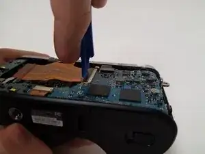
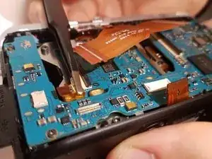
Locate the skinny ZIF cable on the left side of the main board.
-
Disconnect the cable with the tweezers by pulling it away from where the cable is connected.
-
-
-
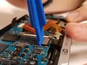
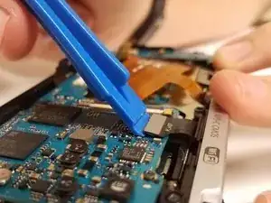
Locate the black cable connected at the top right of the main board.
-
Place the wide-set plastic opening tool underneath the gray connector and carefully pry it up.
-
-
-
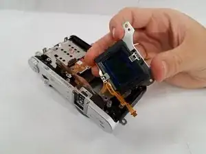
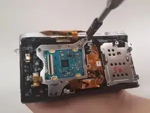
Remove the three black 5-mm T6 type screws using a Torx screwdriver located along the metal casing of the image sensor.
-
Pull the image sensor out and it can now be replaced.
-
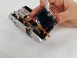
To reassemble your device, follow these instructions in reverse order.
3 commenti
Thanks for this, very helpfull.
I needed to replace the shutter assembly.
For this, next step is to remove the metal top of the camera (a screw on each side and 2 screws in the flash shoe below the spring).
After this the 2 screws on top of the shutter assembly can be removed.
The shutter assy can now be removed although it is somewhat easier if the tripod mount is removed first.
Very helpful. Thanks for posting.
My mode selector is not changing mode as it should, it seems like a contact failure. What shoul I do?
Juan Prekop
prekop -
thanks so much for sharing Well appreciated