Introduzione
Following this guide will ensure a safe and easy way to replace the Input/Output Printed Circuit Board (I/O PCB) in your Samsung Series 9 (NP900X4B-A02) laptop. No other skills are required to to replace this board, which means anyone can accomplish this task.
The I/O PCB is the board that controls most of the interaction between a person and their computer. As with other circuit boards, a problem with your I/O PCB can be difficult to diagnose. Before replacing your I/O PCB, be sure that the board is the cause of the issue.
Before beginning this guide, ensure that your laptop is powered off and disconnected from its power source.
-
-
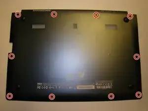
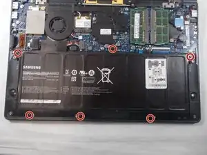
Remove the ten screws along the base using a Phillips #000.
-
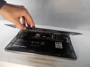
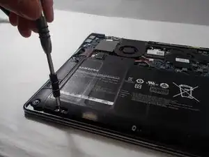
Use a Plastic Opening Tool to pry open the base .
-
-
-
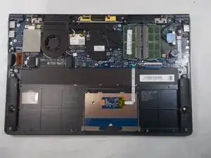
The battery is now unobstructed from your view.
-
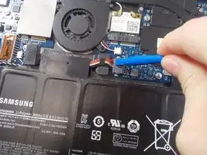
Before removing the battery, use the plastic opening tool to detach the ribbon wire cable that connects the battery to the motherboard.
-
-
-
Use the Phillips #000 screwdriver to remove six screws that are holding the battery in place.
-
-
-
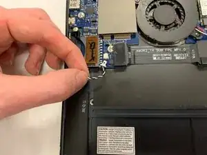
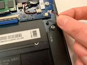
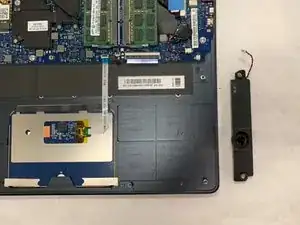
Unplug the right speaker's cable from the motherboard.
-
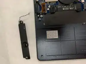
Lift up and remove the right speaker.
-
-
-
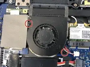
Next locate the two Phillips #0 2.5mm screws on both the top right and bottom left corner of the fan.
-
-
-
After locating the screws, using the Phillips #0 screwdriver, remove the screws from the fan.
-
-
-
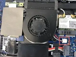
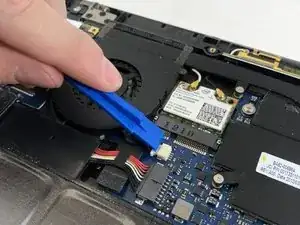
Use the plastic opening tool to remove the cable connector from its housing which is just to the right of the fan.
-
-
-
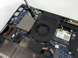
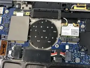
Once the cable has been removed from its housing you are free to remove the fan from the laptop.
-
You can either clean the fan with a computer duster or other cleaner, or replace it with a new one.
-
-
-
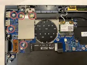
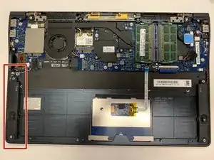
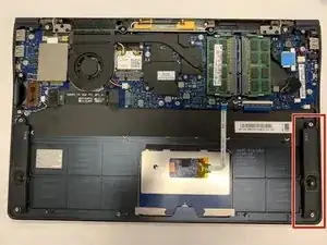
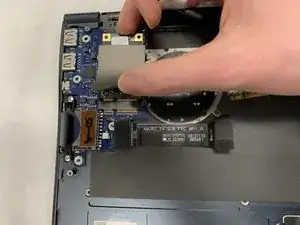
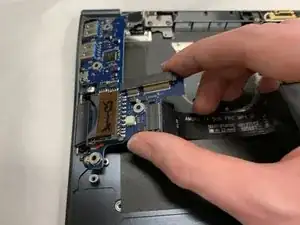
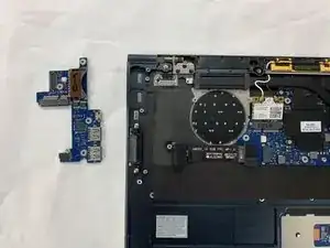
Lift the right side of the I/O PCB and pull to the right to remove it from the laptop casing.
-

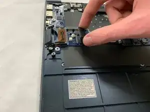
To reassemble your device, follow these instructions in reverse order.