
Introduzione
The Smart UF75 projector uses a curved plastic mirror to shape the projected image. The silver coating is on the front surface of the mirror. This is easily damaged by attempts to clean it.
The mirror is not designed to be replaced. The plastic mirror is glued to a metal support bracket. The only repair option is to transfer the mirror with its support bracket from a donor projector that has a different fault.
Removing the mirror bracket requires first removing all the other electrical and optical parts of the projector as outlined in this guide.
-
-
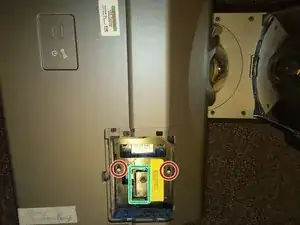
Use a flat screwdriver or coin to remove the flap covering the bulb module
-
Loosen these 2 Philips #2 screws. These screws should stay captive within the bulb module.
-
Lift this handle and pull out the bulb module.
-
-
-
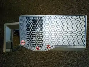
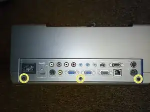
Remove these 3 black 5mm Philips #2 screws from the right side panel.
-
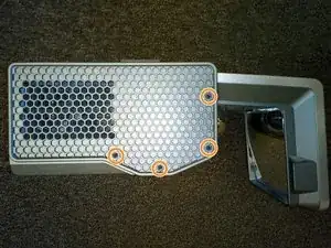
Remove these 4 black 5mm Philips #2 screws from the left side panel.
-
Remove these 3 black 5mm Philips #2 screws from the rear panel.
-
-
-
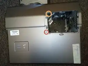
Remove this 7mm Philips #2 screw under the bulb cover.
-
Remove the 7mm Philips #2 screw deep in this hole. A magnetic screwdriver essential for removing and replacing this inaccessible screw.
-
The lid can now be removed by gently prising it off starting at the hole for the bulb.
-
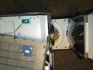
Unplug this cable then put the projector lid to one side.
-
-
-
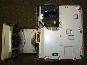
Remove these 11 silver 5mm Philips #2 screws from the metal cover.
-
Unpeel this black card that is stuck to the metal cover.
-
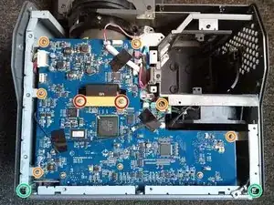
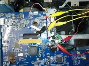
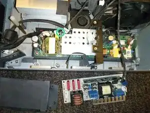
Lift off the metal cover to reveal the main circuit board
-
-
-
Remove these 2 silver 8mm Philips #1 screws and their white plastic washers then unplug the ribbon cable. This plug will drop through the hole in the board when you lift off the board.
-
Remove these 6 silver 8mm Philips #2 screws from the main circuit board.
-
Remove these 2 silver 6mm Philips #2 screws that attach the board of plugs at the back of the projector.
-
-
-
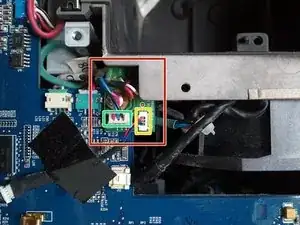
Projectors built in 2010 have a small extra circuit board here. You can skip this step if you have a newer projector without this extra circuit board.
-
Unplug this wire from the small circuit board. Peel back the two pieces of tape holding down the wire, leaving one end of each piece of tape attached to the board for the later re-assembly
-
Remove the other plug from this small circuit board. The small circuit board is now free to come away with the main circuit board.
-
-
-
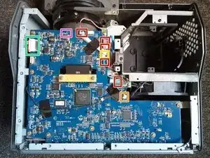
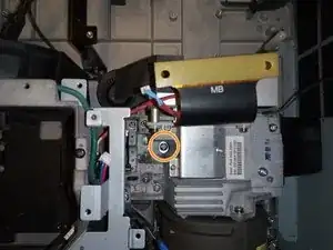
Unplug these 5 plugs. These plugs are stiff but there are no clips or catches to release. I used a combination of pliers and miniature side cutters to grip the two edges of each plug and work it loose.
-
Remove this plug by pressing down the back of the plug to release the catch
-
Gently remove this thin ribbon cable by pulling back the plastic plug then pulling out the cable. Untape the ribbon cable from the board.
-
Later models have an extra wire here that needs to be unplugged.
-
Remove this larger plug by squeezing the two ends to release the clips. On later models, this plug is underneath the board, so you will need to release it while you are removing the circuit board
-
-
-
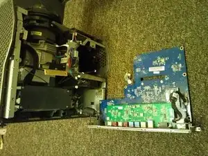
Remove the main circuit board by lifting the board from the back end where the external plugs are attached.
-
Unplug this mains plug.
-
Disconnect the earth lead by unscrewing this silver 5mm Philips #2 screw with its captive serrated washer.
-
-
-
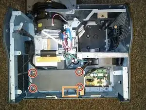
Remove these 3 black 8mm Philips #2 screws holding down the lamp case.
-
And remove this fourth black 8mm Philips #2 screw holding down the front of the lamp housing.
-
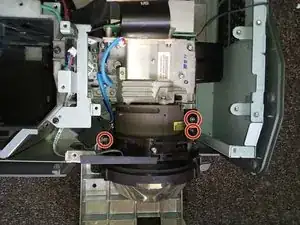
Remove these 2 silver 6mm Philips #2 screws holding down the bulb fan.
-
-
-
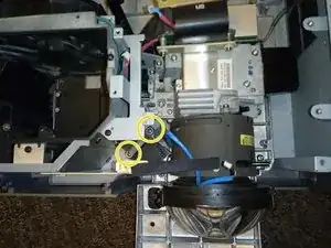
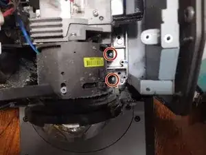
Remove these 3 silver 8mm Philips #2 screws to release bracket that holds the lens adjuster knob.
-
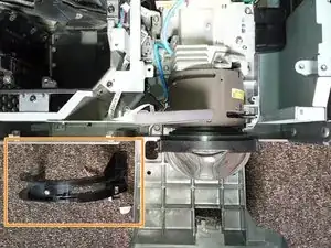
And remove the bracket
-
-
-
Remove these 4 silver 6mm Philips #2 screws to release the top power supply.
-
Peel off this cardboard that is glued to the power supply cover.
-
Unplug the large plugs at each end of the upper power supply and move the power supply out of the way. You can leave the smaller fan wire connected to the power supply.
-
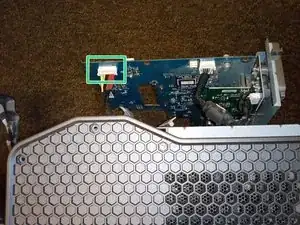
Unplug this thin wire that connects the lid microswitch to the lower power supply so that the optical system is no longer attached to the power supply.
-
-
-
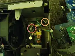
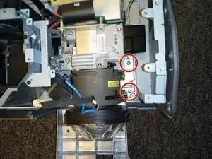
Remove these 3 silver 9mm Philips #2 screws holding down the main optical system.
-
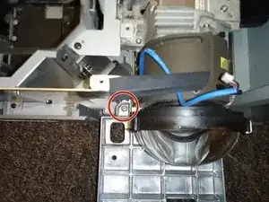
Remove the fourth silver 9mm Philips #2 screw that is buried deep down the hole.
-
-
-
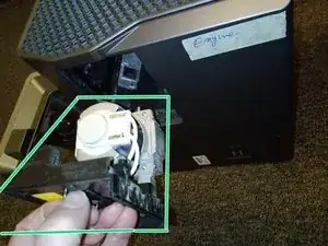
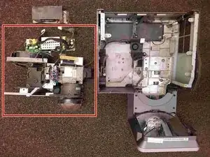
The entire optical system can now be lifted out of the projector.
-
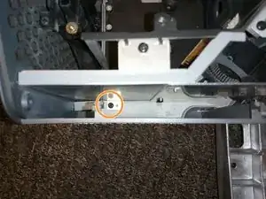
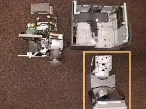
And the mirror bracket can now be lifted off the case
-

To reassemble your device, follow these instructions in reverse order.