Introduzione

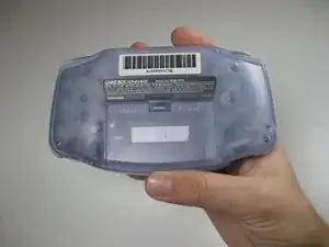
Usa questa guida per smontare tutte o alcune delle parti del Game Boy Advance.

  1. FQtv1v6UntVUhZbZ
    FQtv1v6UntVUhZbZ
    evt4WKJq2JU6NORS
    uV53WW1WLpuX3Xcv
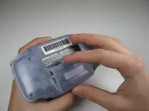
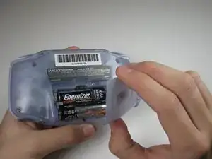
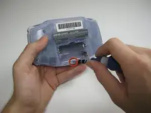
    • Rimuovi il coperchio della batteria posteriore premendo la linguetta e tirando verso l'esterno.

  2. n2BM6E3TNmNQc1vv
    • Rimuovi le sei viti del pannello posteriore utilizzando un cacciavite Y1.

  3. YDNPJjBYq4IIvkO4
    • Rimuovi la vite del pannello posteriore inferiore con un cacciavite Phillips #1.

  4. YjidaLAxBustDHfg
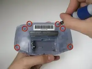
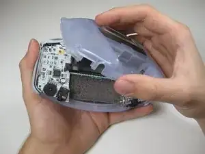
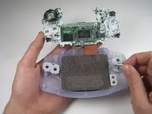
    • Rimuovi il pannello posteriore tirando via con una mano, tenendo ferma la parte anteriore fissata con l'altra.

    • Fai attenzione ai grilletti destro e sinistro, ai pannelli destro e sinistro e all'interruttore di alimentazione che potrebbero cadere mentre il pannello posteriore viene rimosso.

  5. dEkU6llJcUF2igH3
    dEkU6llJcUF2igH3
    PfOcLcSAP6gX2pXX
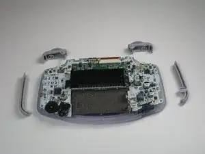
    • Rimuovi i grilletti sinistro e destro sollevandoli e allontanandoli dal sistema.

    • Fai lo stesso per i pannelli laterali.

    • Solo per grilletti pignoli o inceppati. Regola e riaggiusta i grilletti e rimonta. La causa della maggior parte dei trigger inceppati sono i pulsanti posizionati male o inceppati nel loro involucro.

  6. fCOBrNvTgtKZ3WC2
    fCOBrNvTgtKZ3WC2
    buPCeDKOkuwUWENq
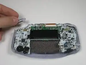
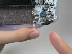
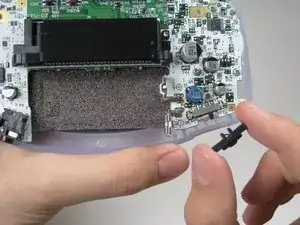
    • Rimuovi l'interruttore di accensione/spegnimento grigio tirandolo verso l'alto e allontanandolo dall'unità. Sostituiscilo con un altro interruttore se necessario.

  7. ODjLTdxT2hd2rIF4
    • Rimuovi le tre viti sulla scheda del circuito con un cacciavite Phillips #1.

    • L'ultima vite a destra non è inclusa in alcuni sistemi Game Boy Advance.

    some motherboards only have 2 screws holding it in place. keep this in mind if you cant find one

    Max R. -

  8. fACppBePP3QF5XAR
    fACppBePP3QF5XAR
    Po2GpWoUg3UvggRU
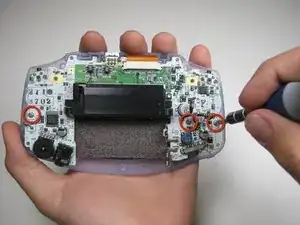
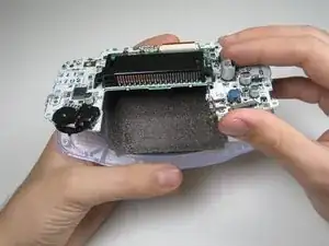
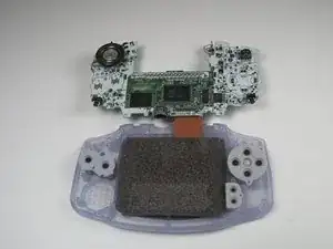
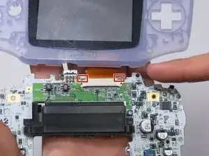
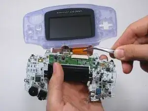
    • Estrai la scheda del circuito dal pannello frontale tirando verso l'alto la parte inferiore della scheda del circuito, mantenendo il cavo a nastro superiore ancora collegato.

    • Fai attenzione a non danneggiare il cavo a nastro superiore sollevandolo delicatamente.

  9. ZhG4WYWRBXIQS1nl
    ZhG4WYWRBXIQS1nl
    TmsfPpSUY2P22rSV
    ZqTvGZGvqcNWTJxb
    • Rimuovi le imbottiture dei tasti in gomma dalle loro tasche.

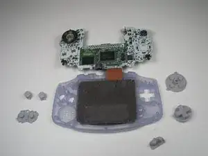
    • Rimuovi i pulsanti di plastica e il D-pad da sotto i gommini con una pinzetta o manualmente.

  10. Y1XGVqih1NjNZbsV
    Y1XGVqih1NjNZbsV
    BqM6MXAjJ3V2XfDh
    ZYQ4E4KRqZy6ME1W
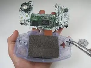
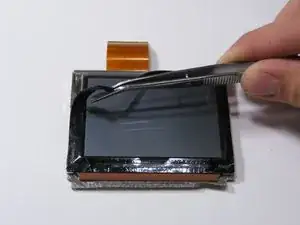
    • Usa uno spudger/una pinzetta/un'unghia per sbloccare la porta del cavo a nastro LCD tirando le linguette grigie sui lati verso l'alto (verso il bordo superiore del PCB).

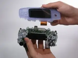
    • Una volta che la porta del nastro LCD è stata sbloccata, il cavo a nastro LCD dovrebbe scivolare fuori molto facilmente e può essere rimosso senza forzare, usando le dita o le pinzette.

    Guide does not indicate that the ribbon cable port should be UNLATCHED before attempting to remove the ribbon cable, I strongly suggest revising this as someone unfamiliar with these style of ports may assume that the ribbon cable is a compression fit and just needs to be "pulled" free of the port.

    This is a terrible idea that will potentially result in tearing the ribbon! Please consider revising guide to add a step to indicate the proper method/detail for unlatching the LCD ribbon port! Thanks :)

    Ben Steel -

  11. StGr2Ks6JuTNdsoo
    StGr2Ks6JuTNdsoo
    fJZogxVx2dKyOrVY
    BGKsVlcA1ufbonoB
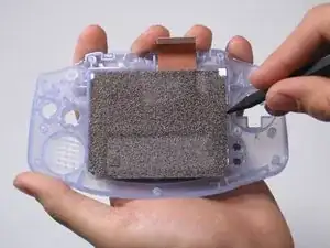
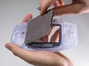
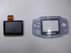
    • Usa lo spudger per sollevare lo schermo dal pannello frontale. Posiziona lo spudger nello spazio direttamente a sinistra del D-pad.

    • Lo schermo e il pannello frontale sono collegati da un nastro adesivo nero che potrebbe strapparsi se non rimosso con cura.

    • Puoi usare un iOpener o un asciugacapelli sull'altro lato del pannello frontale per ammorbidire il nastro nero.

    This is a BAD place to pry on a functioning LCD. I used this exact method, slowly and carefully, and my LCD shattered.

    Instead, remove the lens (it’s worth it to sacrifice the lens adhesive to save your LCD), and gently and slowly press with a gloved thumb on a corner to push it through from the front of the Game Boy. Let the adhesive release itself, don’t force it. If the room is super quiet, you should be able to hear a faint peeling sound, even if you can’t see anything moving. That means you’re doing it right; just wait and it will release.

    trevorsklar -

    Actually you can just pry under the ribbon cable. The LCD has a metal frame there that allowed me to slowly and carefully pry from that point without (re)breaking my LCD.

    trevorsklar -

    Yep. Same thing just happened to me :(

    Robert Carlson -

  12. 6galgqIuLon5Ce6X
    • Utilizza le pinzette per rimuovere il nastro adesivo nero, se necessario.

Adam

Membro da: 21/01/10

807 Reputazione

7 commenti

used this to replace the case and buttons on my GBA worked like a charm thanks!

Josh -

I dont understand. The items in “Tools featured in this teardown" is different from the tools written on the article e.g. Y0 in “featured" but Y1 in the “article”.

darelldechavez -

Bruh thx for

ColdPizza -

Great guide. My dumb ass didn’t see the screws holding the circuit board to the front shell lmao

RikaSprout -

What is the cpu

znlisowski@icloud.com -

I am having difficulty determining the size of the Tri-Point screws used on the Game Boy Advance. As a previous commenter noted the screw driver listed as “Tools Featured in this Teardown” shows a size of Y0, but in the text of the teardown it shows Y1. Can someone please clarify?

bhandl1 -

How do you remove the CPU and SRAM chips?

Steven Steele -