Introduzione
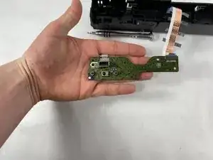
This part has the buttons which controls the device power and the ejecting of the disc tray in order to place in or remove a disc. this part also has a USB port to have a wired connection with another device. This is mounted to the inside of the front panel.
Be careful when removing the screws because it it easy to strip plastic treads so do not force the screws in when reassembling.
-
-
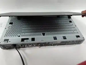
Use a Phillips #2 screwdriver to remove the two 10.5 mm screws that secure the two side panels onto the back of the player.
-
Slide both covers back about a 1/2 inch, then pull them away from the case.
-
-
-
Use a Phillips #2 screwdriver to remove the two 10.5 mm screws on the side of the case, each connecting to a tab on the cover.
-
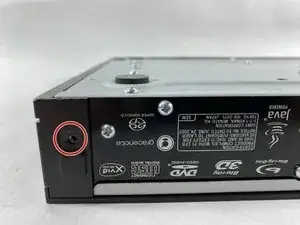
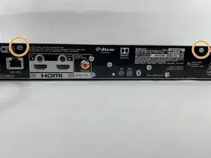
Use a Phillips #2 screwdriver to remove the two 10.5 mm screws (one next to the Wi-Fi logo and one next to the Blu-ray logo).
-
-
-
Press in the tabs found on the front-sides of the case (connected to the front panel).
-
Slide the top cover forward.
-
Lift off the case.
-
-
-
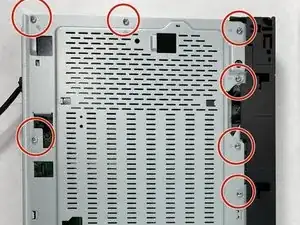
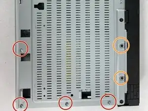
Find the eleven 10.5 mm silver screws and two 6 mm black screws on the perimeter of the silver cover plate.
-
Remove the silver screws using a Phillips #2 screwdriver and the black ones using a Phillips #1 screwdriver.
-
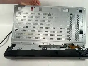
Life the back of the cover up and off of the chasis.
-
-
-
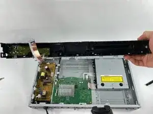
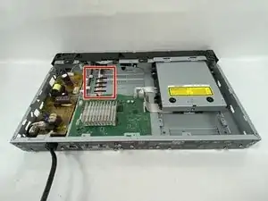
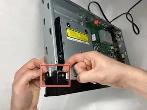
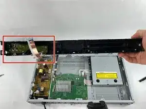
Toward the panel there is a ribbon cable with 4 small black pieces of tape holding it down
-
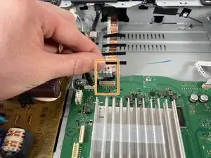
Pull directly up on the ribbon cable to disconnect it from the motherboard
-
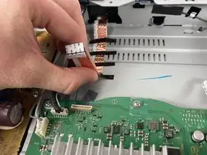
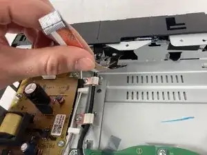
Gently pull the cable back away from the motherboard pulling the tape off with it
-
-
-
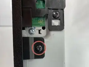
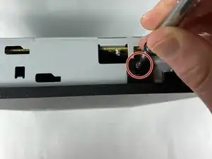
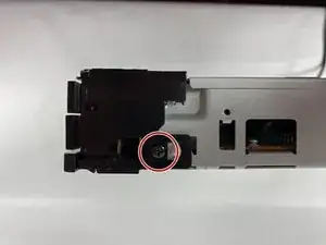
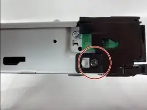
There are screws on every side of the front panel holding it in. Use a #2 Phillips head screwdriver to remove the nine screws.
-
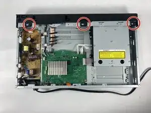
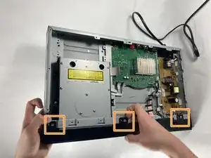
Unscrew the three 10.5 mm long ph #2 screws on the top.
-
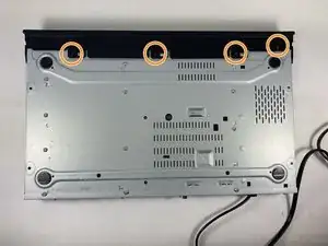
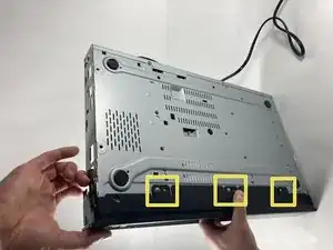
Unscrew the four 10.5 mm long ph #2 screws on the bottom.
-
-
-
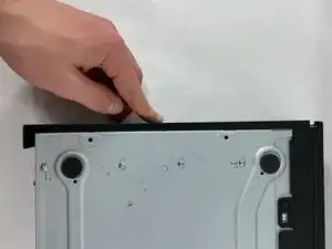
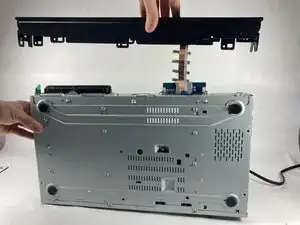
Lift tab on the left side of the device
-
Work your way right, lifting the next tabs. One on the bottom and one the Top
-
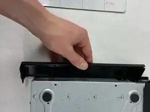
Continue working the tabs on the top and bottom, keeping them from snapping back in place.
-
-
-
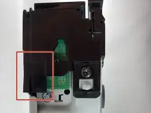
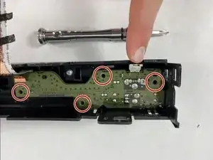
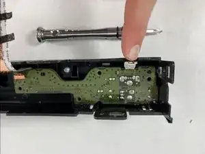
Once the Front Panel is removed, look to the inside of it and find a green circuit board which will be the Personal Control Board (PCB).
-
-
-
Remove the four 10mm screws holding the PCB in place and unscrew them using the #2 Phillips head screwdriver.
-
To reassemble your device, follow these instructions in reverse order. Remember to not force the screw into the holes to not strip the threads.