Introduzione

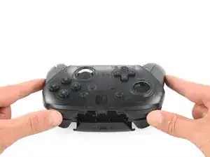
Questa guida ti mostrerà come sostituire i tasti posteriori rotti del Pro Controller Nintendo Switch. I tasti posteriori rotti limitano l'esperienza di gioco ottima con la console Nintendo Switch. La sostituzione di un tasto posteriore del tuo controller ti permetterà di usarlo al suo massimo potenziale. Questa guida richiede di disassemblare completamente il controller. Perciò fai attenzione durante la procedura per assicurarti di non danneggia i circuiti o i connettori piatti all'interno del controller.

  1. iaKRfcPV2HNC5yUK
    • Gira il controller in modo che l'etichetta con il modello sia rivolta verso l'alto.

    • Usa un cacciavite JIS #00 per rimuovere le due viti nere a testa piatta da 8,4 mm che trattengono i manici, posizionate alle estremità degli stessi.

    Be carefull, these screws are super easy to strip even with the right tools.

    Lukas Eberharter -

    I tried editing these instructions after I had trouble with stripping screws, but it doesn't seem to take. The issue is that these are JIS and not Phillips screws. They are VERY similar looking but a Phillips head screwdriver will strip the screws.

    Isaac Webb -

    I tried using a Philips #00 screwdriver but it didn’t work

    vincent ingrassia -

  2. pFHHOlTyvlQ43DOC
    pFHHOlTyvlQ43DOC
    KCE54LsPyGnuWTkW
    UNYZtREEKVfHallZ
    • Rimuovi attentamente le coperture dei manici tirandole via dal corpo del controller.

  3. 3OnYDcOU1gVR2fEG
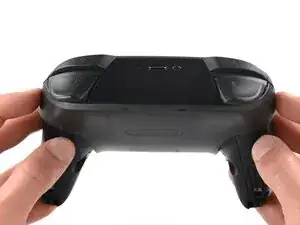
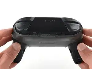
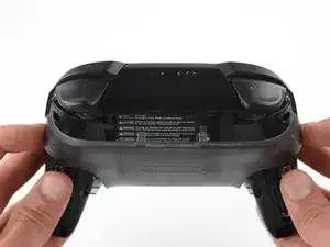
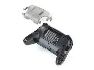
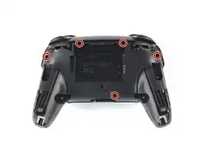
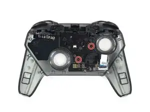
    • Usa un cacciavite JIS #00 per rimuovere le quattro viti argento da 6,8 mm che trattengono la copertura posteriore in plastica trasparente.

  4. Zb3Ool4Evh63KKVd
    Zb3Ool4Evh63KKVd
    E4qBEgOibCQbXlIJ
    jihxJQfDSqclVJnF
    • Prestando attenzione, fai leva sulla copertura in plastica trasparente per rimuoverla.

  5. p4bHAkTpIvuBFIfc
    • Rimuovi la copertura in plastica trasparente.

  6. yUbMYllrTC6sSOGL
    yUbMYllrTC6sSOGL
    6pxWhyQpxoXGbs22
    vEF6WXIGCHUebiZO
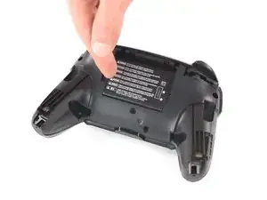
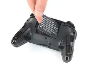
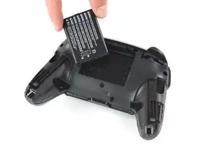
    • Rimuovi la batteria a ioni di litio facendo leva sul suo bordo sinistro con un'unghia o uno strumento per l'apertura in plastica.

    • Basta fare una leggera forza.

  7. 41hYi1SofYMKVF4B
    41hYi1SofYMKVF4B
    IhtOVVcrnx5IBHgJ
    WJ4LvGQlKLhlREns
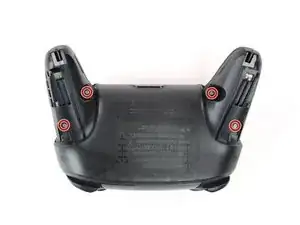
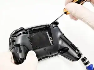
    • Usa un cacciavite a croce Phillips per svitare le cinque viti da 5 mm dal retro del controller.

    the 2 screws up at the top are unreachable with the standard fixit kit just a heads up

    drew -

    Seconded. the screws are located too deep below the plastic slot, and the bit holding bulge is too wide for the small aperture (similarly with the flexible extension). the bit length is too shallow to reach.

    An alternative driver with a much narrower & longer shaft is required, which will likely not come with interchangeable bits.

    Douglas Selby -

    I would say it is possible to reach the top left screw, just not the top right - there is a gap in the top left that allows you to slightly bend the standard driver outward to turn it while still making adequate contact.

    El_Mechacontext -

    An update: I was actually able to remove the top right one in a really hacky way - inserting the Phillips #0 bit into the #4 hex bit, and then using that in the standard driver. This added just enough length to successfully reach and make full contact with the screw!

    El_Mechacontext -

    Using the #4 hex bit as an extension was the exact "hack" I needed to get rid of the drift finally. Thank you. You're a lifesaver.

    Das #4 Hex Bit als Verlängerung für das Kreuzschlitz Bit zu nutzen ist zwar etwas eng, aber es erspart einem wirklich einen zusätzlichen Schraubendreher.

    Techn0magier -

  8. PnIrdtdY4KCyxuKK
    PnIrdtdY4KCyxuKK
    ZBKtxPXnhQuBTaDN
    OZcevYGCPPARFaRx
    • Rimuovi delicatamente la copertura in plastica dal controller.

    • Non rimuovere ancora del tutto la copertura anteriore, in quanto è ancora collegata alla scheda madre tramite un cavo a nastro bianco.

    Didn't realize there is adhesive holding the front cover onto the unit. It's located inside of the handles. Just a bit of force there helped, just be careful of the cable.

    Roger Perez -

    this step is really hard

    XDchlapec -

  9. NpVhXDsYSWmW4tBT
    NpVhXDsYSWmW4tBT
    QXe1DlCMuCXbrveX
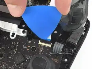
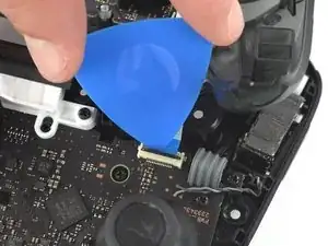
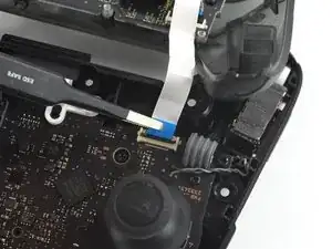
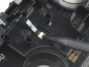
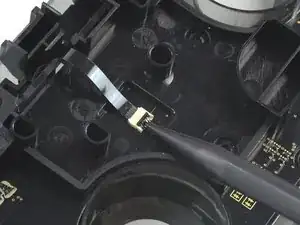
    • Usa la punta di un plettro per aprire l'aletta nera sul connettore ZIF spingendola verso l'alto.

    Having just completed this repair, I noted that this ribbon cable can disconnect on either side. It is easier to disconnect and reconnect from the other side than what is shown in my experience.

    acestronautical -

    @acestronautical is right! much easier to remove the ribbon cable from the button board, connect to the base board and then connect back to the button board. Thank you @acestronautical

    Joe Rickerby -

  10. 3qj6VtFJtKAHHm6I
    3qj6VtFJtKAHHm6I
    YJvaLXngDhvHF1Gr
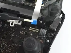
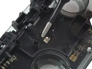
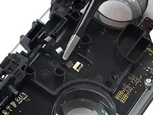
    • Usa le dita o un paio di pinzette a punta arrotondata per scollegare il cavo di interconnessione dal suo connettore.

    You don't need to disconnect this as long as you are fine with keeping it close by so as not to rip the ribbon cable.

    Caden Helm -

  11. OpC2vBHXBB35uAQ4
    • Rimuovi la copertura anteriore.

  12. d2TaQbKySN1dMQ4M
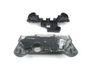
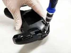
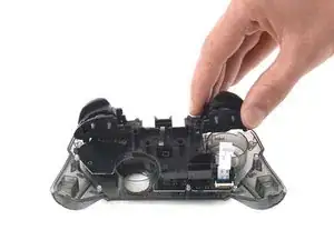
    • Rimuovi le due viti da 6.8 mm sulla parte superiore della scheda circuitale con un cacciavite Phillips.

  13. GuqsGsnEcB2nVvxX
    GuqsGsnEcB2nVvxX
    RVyZNQZQ3Depk22x
    • Usando uno spudger alza il blocco che tiene fermo il connettore ZIF.

  14. tlAmOo6KaKA6USWf
    tlAmOo6KaKA6USWf
    6GTbU2NmR3QpSBZC
    • Rimuovi il cavo piatto nero dal suo connettore.

    • Sarà necessaria pochissima forza per rimuovere il cavo piatto.

    What do I do if the connector snaps off? Is it fixable with solder or electrical tape or should I give up hope?

    Jack Frost -

    This ribbon cable is difficult to reconnect, quality tweezers are required. I was unable to slide the ribbon cable in to where I could no longer see the traces. Take note of how much ribbon cable is exposed before disconnecting so that you can have an easier time judging when the cable is fully inserted upon reconnecting.

    acestronautical -

  15. ZHXWOMSOZhgEMnTA
    ZHXWOMSOZhgEMnTA
    PgCpkYRsAuKmefFR
    • Rimuovi i pulsanti posteriori dalla struttura in plastica.

Conclusione

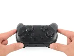
Per riassemblare il dispositivo segui le istruzioni nell'ordine inverso.

Simon Lin

Membro da: 10/10/19

364 Reputazione

5 commenti

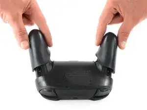
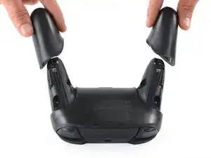
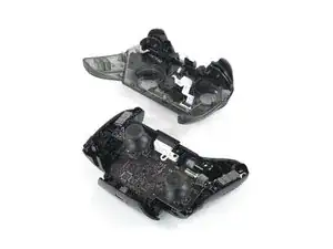
This guide does show how to remove the trigger/bumper casing and board from the controller but does not show how to remove the triggers/bumpers from the casing they are in.

Boushi Adams -

Yeah, this is a pretty big point to be missing, especially with the Flex Cable for the shoulder button inputs being right beside the post you need to pull out to remove the ZL and ZR buttons. Guidance on how to remove the post safely without damaging the cable would be great.

Alex Crocker -

Used the guide to repair a shattered right shoulder button successfully. Thanks!

Christian -

After reinstalling the shoulder buttons I have found them to stop working, all four, I checked my ribbon cable from the buttons to the board and even replaced it. I also confirmed the ribbon cable connector on the main board is working as well. Can anyone make any further troubleshooting suggestions?

David -