Introduzione

Questa guida illustra le modalità di sostituzione dell'unità SuperDrive del computer portatile (richiede un'unità SuperDrive SATA).

  1. qPsGdXwUZZBT6RJa
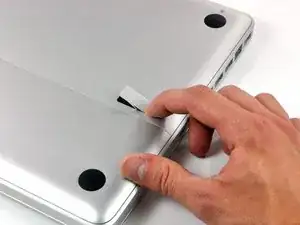
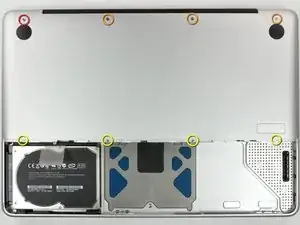
    • Con il case chiuso, posizionare l'Unibody capovolto su una superficie piatta.

    • Premere il lato scanalato della chiusura di sgancio dello sportello di accesso, affinché sia possibile prendere l'estremità libera con le mani. Sollevare la chiusura di sgancio finché non è in posizione verticale.

    This is not a a1278 unibody MacBook Pro. A1278 MacBooks backs are one solid metal piece not two separate pieces. This guide is for a different MacBook Pro.

    Brad Burgeson -

    This guide isn’t for a pro; it’s a MacBook unibody.

    Nicholas -

    So, it turns out that Apple used the model code A1278 for quite a few different Mac models, including both Pro and non-Pro versions! This guide is for the non-Pro Macbooks. There’s also one for the Pro models with the same A1278 identifier.

    tempelmann -

  2. Pf4wGUpXWyJ3tAfH
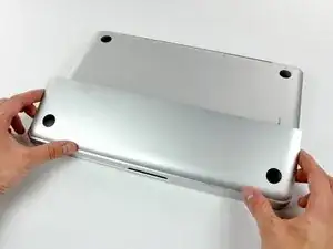
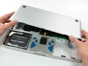
    • Adesso, lo sportello di accesso dovrebbe essere abbastanza rialzato per sollevarlo e rimuoverlo dall'Unibody.

  3. WkwQip2DfR1iJLMX
    • Verificare che la chiusura di sgancio dello sportello di accesso sia in posizione verticale prima di procedere.

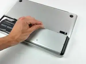
    • Prendere la linguetta di plastica bianca ed estrarre la batteria, rimuovendola dall'Unibody.

    Great tutorial ! great step !

    Leo Etcheverry -

    Even though it’s specifically stated, you have to make sure the access door latch is vertical or the battery won’t be removable.

    Henry Kim -

  4. mgYUuNTR1BjI1A6i
    • Rimuovere le otto viti seguenti, che fissano il case inferiore al case:

    • Una vite con testa a croce da 3 mm.

    • Tre viti con testa a croce da 13,5 mm.

    • Quattro viti con testa a croce da 3,5 mm.

    On my model, it seemed the top-left was 3.5mm and the bottom 4 were 3 mm.

    Jim -

    Make sure you have a good quality Phillips screwdriver. Mine had removable tips and had a small play at the connection. As a result I didn't have a good feel and damaged my screws (those securing the fan and the top left in step 23). Game over for me installing new thermal paste...

    Be very carefull with your screws! Especially those on the inside.

    Nickolas Michelinakis -

    You can get away with a Phillips #00 for many of the screws involved but the 4 at the bottom case split are likely to strip if you don’t use a JIS #00 or, in a pinch, a Phillips #000.

    Bill Cole -

    I used the Phillips #00 tip from my Pro Tech Toolkit, and it worked well enough. But yes, maybe #000 might have been better on the lower row of screws. Note to myself: Always read the comments first.

    Les Kitchen -

    When replacing these screws, the order to replace them in is as follows:

    1, Top left

    2. Top right

    3. Top center-left

    4. Top center-right

    5. Bottom center-right

    6. Bottom center-left

    7. Bottom right

    8. Bottom left

    I hope this information is helpful.

    facebook -

    I followed my usual process of putting in all the screws loosely, then tightening them gradually in distributed pattern, to help ensure that the panel settles in place evenly. But maybe some orders are better.

    Les Kitchen -

  5. EZrPgfOVIaaIsXLR
    • Con entrambe le mani, sollevare il case inferiore da quello superiore.

    Thanks for the guide!

    It's implicit in the two photos, but worth mentioning because it blocked my progress in this step for a bit: You have to put the release latch back into its horizontal, closed position before you can lift off the lower-case panel.

    Les Kitchen -

  6. XKDUxSpNsBtZLsgd
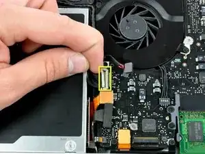
    • Utilizzare l'estremità piatta di un inseritore per rimuovere il connettore del subwoofer estraendolo dalla scheda logica.

    Me, too, broke the subwoofer connector from the motherboard. I'd suggest removing the padding first so that you can see what kind of connector it is, then pry it loose (insert spudger where the cables enter the connector).

    petterwolff -

    DO NOT REMOVE THE SUBWOOFER CONNECTION. Step 6 IS NOT NESCESSARY.

    You can complete this guide without doing step 6 just BE CAREFUL as you already should be.

    kenneth rhem -

    The subwoofer cable is NOT removable on some models, attempting to remove it, brakes it off the circuit board and them you are @@%#$$, like me. Thanks iFixit. Also it is not necessary to remove it to replace the optical drive.

    todd -

    Oops, I followed Step-6 and my subwoofer connector came off from the motherboard!!! Please suggest me what needs to be done now?

    Srinivasan -

    Happened the same to me ... step 6 is a @%#$$. You should put now a way to repair the damage done. I just have four small tin marks on the board ...

    stratorick -

    Happened the same problem to me ... step 6 is a @%#$$**%%#. You should put now a way to repair the damage done. I just have four small tin marks on the board ... and looking to sky for help

    Badruddin Hisbani -

    Just “4 small tin marks” is what the the motherboard half of the subwoofer connector looks like.

    Bill Cole -

    There are two variants of this connector. In one, there are pins that come up from the motherboard and the connector can be pried directly up without damage.

    The other variant of the connector that everyone commenting here has is soldered to the motherboard. To repair this type, first pull off the small square of foam padding on top of the connector. Then gently pull out the four black and red wires, leaving the soldered connector attached to the logic board. After you have installed the new speaker and subwoofer, you will remove the connector on the replacement component and carefully feed the red and black wires into the connector that is still attached to the motherboard (paying careful attention to their correct order). Then replace the square of black foam.

    If you have removed the soldered on the connector, your two options are to solder it on yourself or to find a repair shop that can do that for you. There are instructables online for soldering tiny components that can help you.

    bike -

    Reading all of these comments prior to beginning the work, I didn’t even try to investigate the type of connector my laptop had. I just DIDN’T attempt removal of this connector, worked around it, and as others have mentioned, it is truly unnecessary to remove this connector. You can move the subwoofer (after removal of its other screws) out of the way just enough to slip out the old drive and slip in the new drive.

    Henry Kim -

  7. IXOVdXxYBnnBDaPx
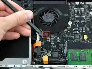
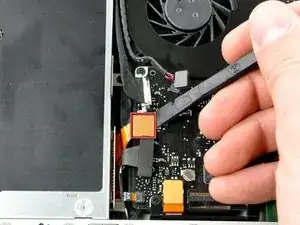
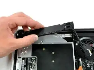
    • Scollegare il cavo della fotocamera, estraendo l'estremità maschio direttamente dal connettore femmina.

    The lack of warning “Be careful not to pull up on the cable as you remove it from the socket.” here, as is displayed on a similar step on the “MacBook Unibody Model A1278 AirPort Card Replacement” guide, has caused me to break the cable. My WiFi is not working anymore. How can I replace only this cable? Thank you.

    Ismael Neiva -

    Bonjour J’ai eu le malheur de toucher à ce câble et depuis je n’ai plus de retro-éclairage sur mon écran. Est-ce lié ?

    Hello I had the misfortune to touch this cable and since then I have no more backlight on my screen. Is it related? (but the computer works fine when I plug in a screen)

    christophe.arnaud -

  8. 2XOdCpbTpAwKr5Sq
    • Utilizzare un inseritore per rimuovere il connettore dell'unità ottica dalla direttamente dalla scheda logica.

  9. fPZsRxoY2MREdCWN
    • Rimuovere le due viti con testa a croce che fissano il subwoofer al case superiore.

    • La vite più lunga si trova a destra.

    Longer screw was on the Left for me.

    amiller770 -

    Left: 3.7 mm

    Right: 4.0 mm

    As I measured with a vernier caliper.

    nickjg -

  10. hclnehUpyFoNxWvW
    • Il subwoofer è ancora collegato all'altoparlante destro, pertanto non deve essere ancora rimosso completamente.

    • Sollevare subwoofer dall'unità ottica e riporlo sopra il computer.

  11. jGfM5vNGHBhlgqNN
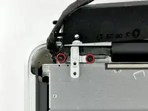
    • Rimuovere le due viti con testa a croce che fissano la staffa del cavo della fotocamera al case superiore.

    • La vite all'estrema sinistra potrebbe restare nel cavo della fotocamera.

    This step is not necessary. Drive can be released without removing the screws.

    mcbohdo -

    If you’re replacing the subwoofer, you DO need to remove the left screw but not the right screw. This is fortunate, because if you are stuck with a Phillips #00 instead of a JIS #00 screwdriver, you may well strip the heads of these screws.

    Bill Cole -

  12. bMaKvVUPBeQkHWLf
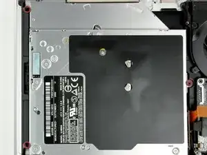
    • Rimuovere le tre viti con testa a croce da 2,5 mm che fissano l'unità ottica al case superiore.

    The lower left screw hole of the replacement drive purchased from iFixit doesn’t align with the screw hole of the body of the computer. Doesn’t seem to be a problem as the drive seems to be quite stable with the other 2 screws, and the “fit” within the drive area.

    Henry Kim -

  13. Wma3oP1Co6x3UfAp
    • Sollevare l'unità ottica dal bordo destro ed estrarla dal computer.

    • Il cavo del disco rigido potrebbe scollegarsi dalla scheda logica durante la rimozione dell'unità ottica. Verificarne che sia collegato durante il riassemblaggio.

Conclusione

Per riassemblare il dispositivo, seguire queste istruzioni in ordine inverso.

Walter Galan

693762 Reputazione

0 commenti