Introduzione
Usa questa guida per sostituire il gruppo display del tuo Samsung Galaxy S4.
-
-
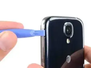
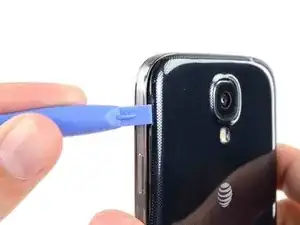
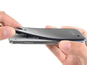
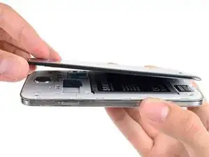
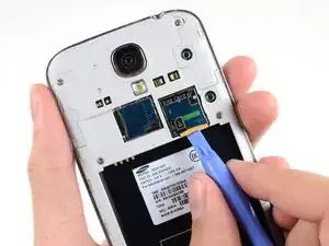
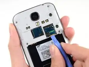
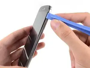
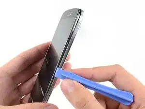
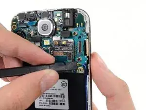
Fai leva, con uno strumento di apertura in plastica o con un'unghia, nella fessura a sinistra della fotocamera posteriore, vicino al pulsante di accensione.
-
-
-
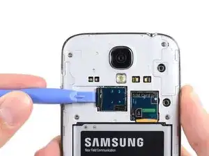
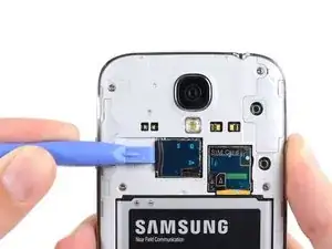
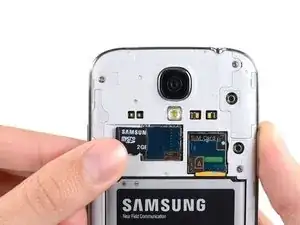
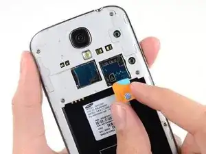
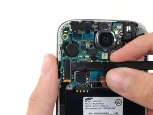
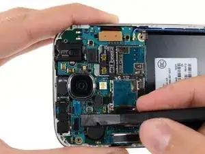
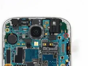
Usa l'estremità piatta di uno spudger o un'unghia per spingere la scheda microSD lievemente più in profondità nel suo alloggiamento, finché non senti un clic.
-
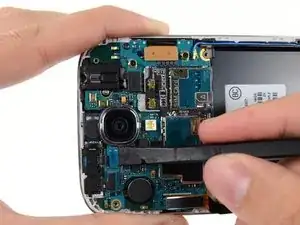
Dopo il clic, lascia andare la scheda, che a questo punto uscirà dal suo alloggiamento.
-
Rimuovi la scheda MicroSD.
-
-
-
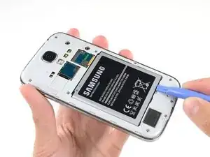
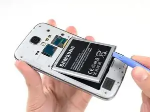
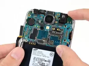
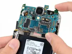
Inserisci uno strumento di apertura in plastica o un'unghia nella rientranza del vano della batteria e solleva la batteria stessa.
-
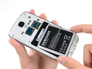
Rimuovi la batteria dal telefono.
-
-
-
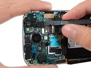
Usa l'estremità piatta di uno spudger o un'unghia per spingere la scheda SIM lievemente più in profondità nel suo alloggiamento, finché non senti un clic.
-
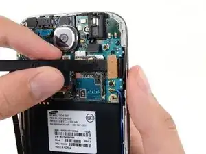
Dopo il clic, lascia andare la scheda, che a questo punto uscirà dal suo alloggiamento.
-
Rimuovi la scheda SIM.
-
-
-
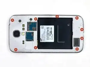
Rimuovi le nove viti Phillips #00 da 4,0 mm che fissano il telaio intermedio al gruppo display.
-
-
-
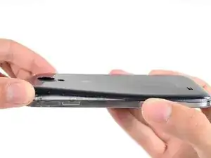
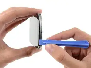
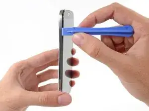
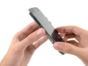
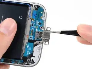
Iniziando dal lato del telefono con i pulsanti del volume, inserisci il tuo strumento di apertura in plastica tra la cornice cromata attorno al vetro del display e il bordo laterale cromato più grande. Cerca la fessura tra le due parti.
-
Fai scorrere lo strumento di apertura lungo la giunzione, separando le clip in plastica mentre procedi.
-
-
-
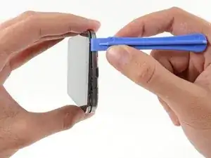
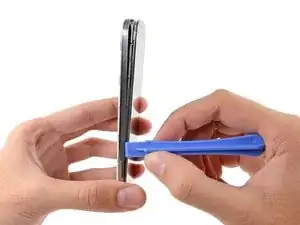
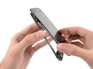
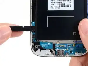
Continua a far leva lungo l'angolo del telefono.
-
Fai scorrere il tuo strumento di apertura lungo la giunzione tra il telaio centrale e il display nella parte inferiore del dispositivo, staccando altre clip in plastica.
-
-
-
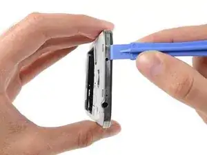
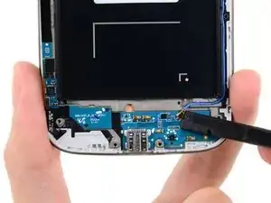
Ancora una volta, fai leva lungo l'angolo, fino al lato del pulsante di accensione.
-
Fai scorrere lo strumento di apertura lungo la fessura.
-
-
-
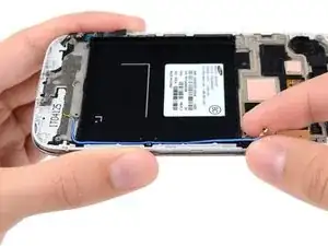
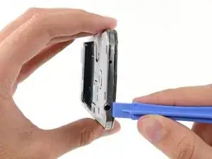
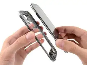
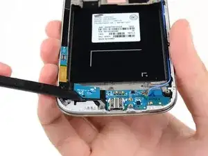
Continua a far scorrere lo strumento di apertura attorno alla parte superiore del telefono, staccando le ultime clip e liberando il telaio intermedio dal gruppo display.
-
-
-
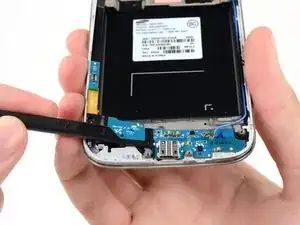
Usa l'estremità piatta di uno spudger per staccare il connettore della scheda USB.
-
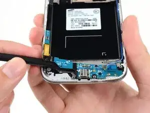
Scollega il connettore del cavo della fotocamera anteriore.
-
Stacca il connettore del cavo del gruppo altoparlante voce.
-
-
-
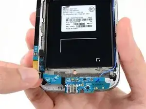
Scollega il connettore del gruppo del jack cuffie.
-
Stacca il connettore del cavo del display/digitizer.
-
Scollega il connettore del cavo dell'antenna.
-
-
-
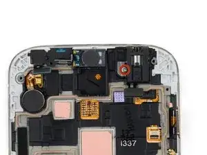
Rimuovi la singola vite Phillips #00 da 2,4 mm che fissa il gruppo jack cuffie al gruppo display.
-
-
-
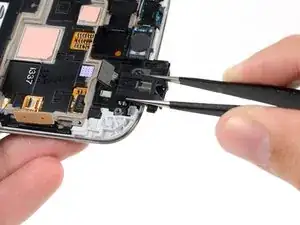
Se è presente, rimuovi la vite Phillips #00 da 2,4 mm che tiene in posizione la staffa superiore del gruppo display.
-
Rimuovi la staffa superiore del gruppo display dal pannello.
-
-
-
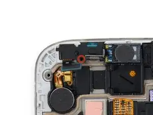
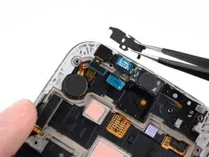
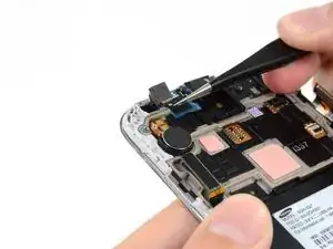
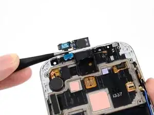
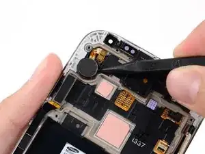
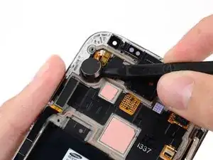
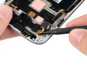
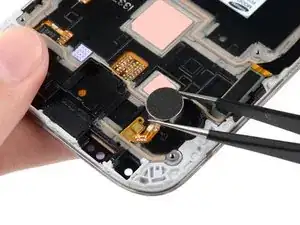
Inserisci la punta di uno spudger sotto il motore di vibrazione per liberarlo dall'adesivo che lo tiene attaccato al gruppo display.
-
Usa la punta di uno spudger per staccare dal gruppo display il cavo del motore di vibrazione.
-
-
-
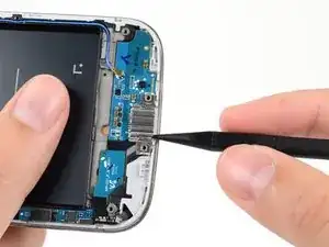
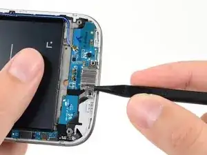
Inserisci delicatamente la punta di uno spudger tra la porta USB e la staffa della porta USB per staccare uno dei lati della staffa dal distanziale che lo tiene in posizione.
-
-
-
Disconnetti dal cavo della scheda USB il cavo del pulsante soft. In questa fase devi prestare particolare attenzione: una volta che hai staccato il cavo, allontanalo con cautela dalla scheda USB.
-
Scollega dalla staffa USB il cavo del connettore dell'antenna.
-
-
-
Inserisci delicatamente l'estremità piatta di uno spudger sotto la scheda USB per liberarla dall'adesivo che la tiene in posizione.
-
-
-
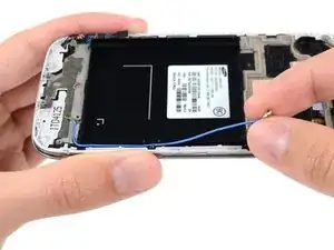
Stacca e rimuovi il cavo del connettore dell'antenna dal suo canale sul retro del gruppo display.
-


Per rimontare il tuo dispositivo, segui queste istruzioni in ordine inverso.

28 commenti
HELP! step 28 just ends how do I insert the new one, how do I resemble the parts that used adhesives to stick?
Tom -
Nearly all the guides end like this, you just need to work backwards through the steps using the new hardware.
Just work backwards like Nick stated. I usually reverse assemble the parts I take off so I know the order in which I need to put them back in.
Just run it along its track. Use a plastic spudger to push it down. Use 3m double sided adhesive tape to re-attach parts that require adhesive.
What is the difference between an AT&T digitizer and a Verizon digitizer? How interchangeable are they?
Martin -
I believe the digitizer is the same but if you buy the digitizer with assembly (frame) there is a difference between the models. Here are the model numbers for all the versions. I545 (Verizon) , I337 (AT&T), L720 (Sprint), M919 (T-Mobile), I9500 (International), i9505 (International)