
Introduzione
Prerequisito per rimuovere il gruppo scheda logica (scheda logica + dissipatore, scheda AirPort ecc.). Utilizzata per le guide sulla scheda logica e sul case superiore.
Strumenti
-
-
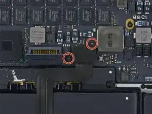
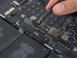
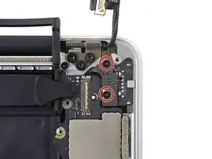
Rimuovi le due viti Torx T5 da 2,2 mm che fissano la copertura del connettore del cavo del touchpad sulla scheda logica.
-
Rimuovi la copertura.
-
-
-
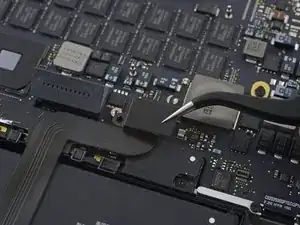
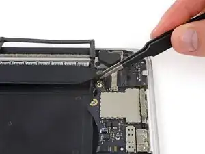
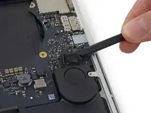
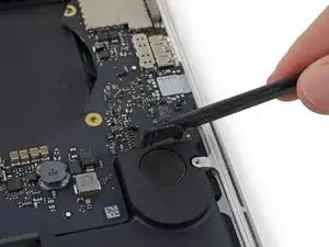
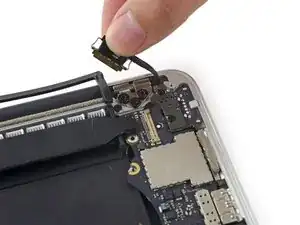
Usa l'estremità piatta di uno spudger per disconnettere il connettore del cavo del touchpad dal suo zoccolo sulla scheda logica.
-
-
-
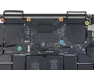
Rimuovi le seguenti sei viti che fissano il gruppo della scheda logica al case superiore.
-
Una vite Torx T5 da 3,8 mm
-
Due viti Torx T5 da 5,7 mm
-
Una vite Torx T5 da 5,6 mm (color argento e con una testa più alta rispetto alle altre)
-
Una vite Torx T5 da 2,6 mm
-
Una vite Torx T5 da 3,2 mm
-
-
-
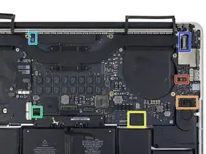
I passi seguenti illustrano in dettaglio la disconnessione di questi sei connettori. Accertati di leggere ogni passo, perché questi connettori sono di tipi diversi e si staccano in modo differente tra loro.
-
Cavo microfono
-
Cavo altoparlante sinistro
-
Cavo dati tastiera
-
Cavo altoparlante destro
-
Cavo retroilluminazione tastiera
-
In fase di riassemblaggio, assicurati di aver ricollegato tutti questi connettori e che siano completamente in posizione nelle loro sedi.
-
-
-
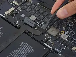
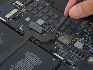
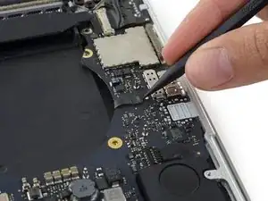
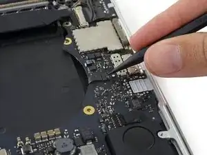
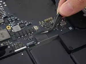
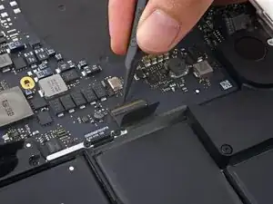
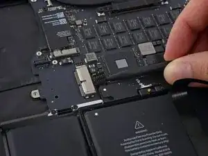
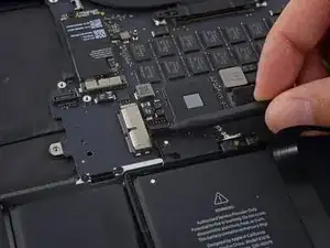
Usa l'estremità di uno spudger per sbloccare la linguetta di fissaggio sullo zoccolo ZIF del cavo a nastro del microfono.
-
Tira fuori dal suo zoccolo, in direzione parallela alla scheda logica, il cavo a nastro del microfono.
-
-
-
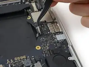
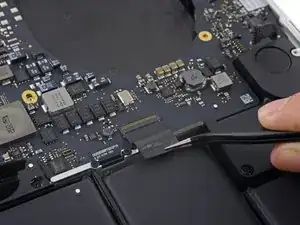
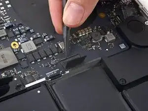
Usa l'estremità piatta di uno spudger per sollevare il connettore dell'altoparlante sinistro e staccarlo dal suo zoccolo sulla scheda logica.
-
Piega con delicatezza il cavo per allontanarlo dalla scheda logica.
-
-
-
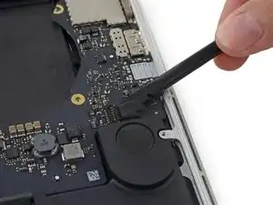
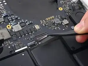
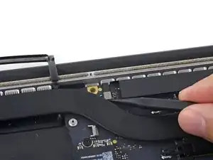
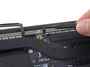
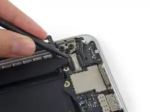
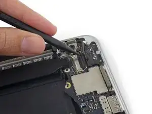
Usa la punta di uno spudger per sganciare la linguetta di bloccaggio sullo zoccolo ZIF del cavo dati della tastiera.
-
Tira fuori dal suo zoccolo il cavo dati della tastiera. Attenzione, devi tirare in direzione parallela alla scheda logica e non verso l'alto.
-
-
-
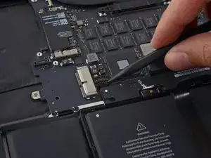
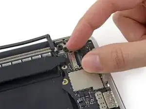
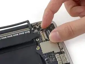
Usa la punta di uno spudger per staccare il connettore dell'altoparlante di destra, sollevandolo dal suo zoccolo sulla scheda logica.
-
Piega con delicatezza il cavo per allontanarlo dalla scheda logica.
-
-
-
Usa la punta di uno spudger per sollevare il connettore della retroilluminazione della tastiera dal suo zoccolo sulla scheda logica.
-
-
-
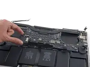
Usa la punta di uno spudger per sganciare il blocco del cavo dati del display e ruotalo verso il lato della porta di alimentazione MagSafe2 del computer.
-
-
-
Tira fuori dal suo zoccolino sulla scheda logica il cavo dati del display.
-
Con delicatezza piega il cavo dati del display verso la cerniera del display, per rendere accessibili le viti sulla scheda MagSafe2.
-
-
-
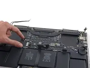
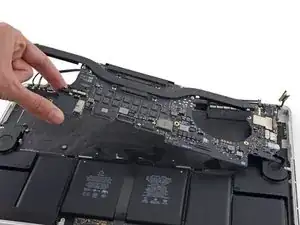
Solleva e tira fuori dalla parete interna del case superiore l'intero gruppo della scheda logica.
-
Per rimontare il tuo dispositivo, segui queste istruzioni in ordine inverso.
I'm confused why it's necessary to remove the entire logic board to replace the right speaker?
Don't you just need to remove the I/O board for the right speaker?
Steve Rieck -