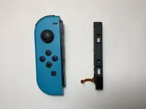
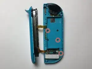
Introduzione

La guida di carica rotta causa l'impossibilità di connettere il Joy-Con direttamente alla Nintendo Switch o di caricarlo. Questa guida ti mostrerà come sostituire la guida di carica sul Joy-Con sinistro.

Prima di eseguire questa procedura, controlla se ci sono dei contatti piegati sulla guida di carica che si possono ripiegare in posizione. Se possibile, controlla se il Joy-Con può essere caricato da una fonte esterna o se il problema è con il sensore di carica sulla Nintendo Switch.

Se il problema è sul sensore guida della Nintendo Switch, segui questa guida: Sostituzione sensore guida Joy-Con sinistro Nintendo Switch

  1. g4PWqBPqfcjppyGm
    g4PWqBPqfcjppyGm
    iYbDvoUOFTY2CCqG
    • Usa un cacciavite Tri-Point Y00 per svitare le quattro viti da 6 mm sul retro del Joy-Con.

  2. iSpjOFpFEkIkLVpB
    iSpjOFpFEkIkLVpB
    5lQVnarIVbKiOJps
    dac4ubPId2MBfFFB
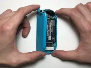
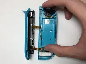
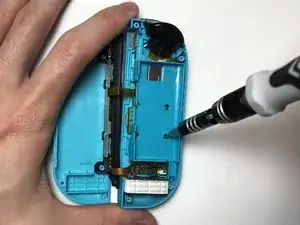
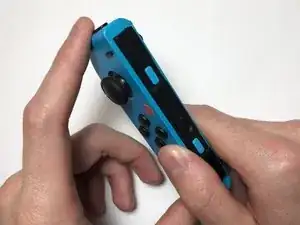
    • Infila un plettro nella parte inferiore del Joy-Con, quindi fallo scorrere verso i tasti L e ZL.

    • Solleva la copertura posteriore del Joy-Con e appoggiala di fianco.

    • Stai attento mentre rimuovi la copertura posteriore in quanto è collegata alla guida di carica e alla scheda madre con due cavi a nastro. Potresti danneggiare il dispositivo se la tiri via.

  3. pHjMtMTIOKSHhqF2
    pHjMtMTIOKSHhqF2
    x5hMXlwnNDvPyNax
    fO1rnSKTLHkZ1t5T
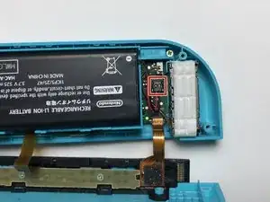
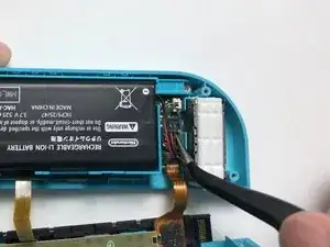
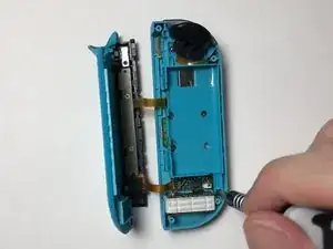
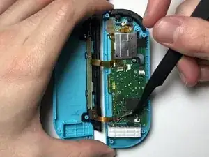
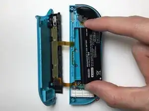
    • Infila uno spudger o uno strumento di apertura sotto i cavi della batteria e scollega il suo connettore dalla sua presa sulla scheda madre.

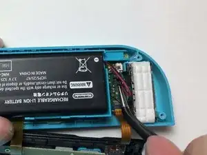
    • Dopo aver scollegato il connettore della batteria dalla presa, solleva la batteria dal telaio intermedio.

    • Ti consigliamo di usare uno spudger per questo passaggio se possibile. Altrimenti usa uno strumento anti ESD.

  4. WGTwvnsOLGixZwnR
    WGTwvnsOLGixZwnR
    ecJFHgvW2Mq3sjki
    jrTtNWS5EVv2qqDX
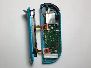
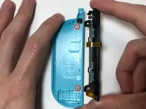
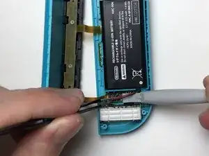
    • Svita le tre viti a croce Phillips #000 dorate da 3 mm che tengono fermo il telaio intermedio.

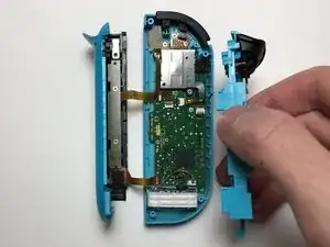
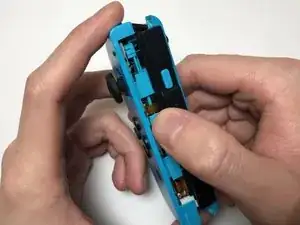
    • Solleva il telaio intermedio dalla scheda madre e appoggialo di fianco.

  5. ZkDew1pKOfQnUGdx
    ZkDew1pKOfQnUGdx
    JGntP2qcoraHEMKk
    EXWFmOIELqlxCVlv
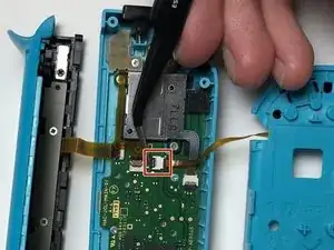
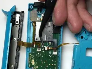
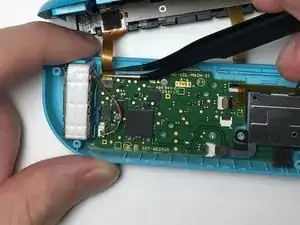
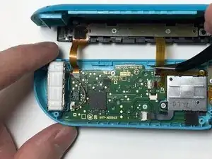
    • Scangia il connettore ZIF che fissa il cavo a nastro del telaio intermedio alla scheda madre.

    • Usa delle pinzette per sfilare delicatamente il cavo a nastro dal connettore ZIF.

    This step (disconnecting the midframe cable) is not strictly necessary, but if you don’t do it the frame can get in the way during reassembly.

    Guy Bolton King -

  6. M3YgTmKEVA2VEGCl
    M3YgTmKEVA2VEGCl
    WvdQKhHvNh6Nvser
    qa4q1RGVnwR2mPnR
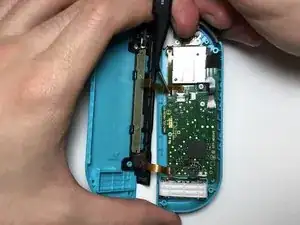
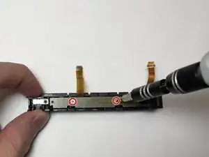
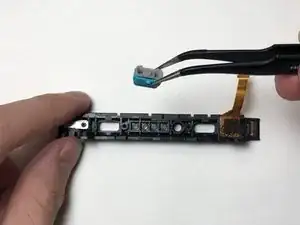
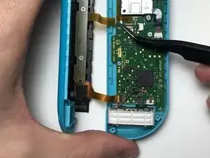
    • Scangia i due connettori ZIF che fissano i cavi a nastro della guida di carica alla scheda madre.

    • Usa delle pinzette per sfilare delicatamente i cavi a nastro dai connettori ZIF.

    How do you unlatch the connections.

    Winston Buentello -

    The top connector has a latch; raising the cable slightly or prising in the slot on the side will release it. There is no latch on the bottom connector; just gently ease the cable out.

    Guy Bolton King -

    The bottom connector absolutely DOES have a ZIF connector, but it's on the opposite side. The tweezers in the second picture are pointing directly at the connector, and it slides up to the left (from the perspective of the picture).

    Rob Hulson -

    That little grey piece on the bottom connector flew off the connector when I put a spudger under it. I can't get it back on regardless of what I've tried, so I'm likely to leave it off rather than risk bending pins. Looks like this little grey piece is wedged between two tuning fork shapes for each pin. If anyone knows the connector name I'd love to take a look at the datasheet as the disconnect/reconnect is making no sense to me.

    Bo Buckley -

    Took me ages to figure out how to put it back on. Just make sure you lift it up to rotate it rather than push it back parallel with the board (like some other connectors). See here for how to replace it if it flies off (and you can find it) :D

    Repositionnement du clapet de connecteur de nappe flexible

    Bo Buckley -

  7. d6bwAuXNmWj13wXo
    d6bwAuXNmWj13wXo
    2NmmwUAdTbhnvWtn
    kyfgACC2CLMRKEig
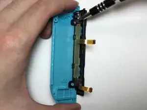
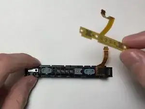
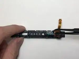
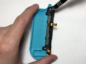
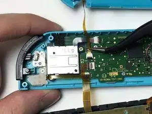
    • Svita le due viti a croce Phillips #000 da 2 mm che fissano la guida di carica alla copertura posteriore.

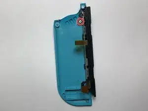
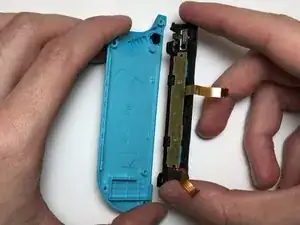
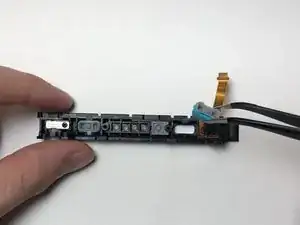
    • Rimuovi la guida di carica dalla copertura posteriore.

    • C'è del nastro adesivo che aiuta la guida di carica a stare ferma sulla copertura posteriore. Quando posizioni la nuova guida di carica sulla copertura posteriore, ti consigliamo di sostituire anche l'adesivo per avere un migliore supporto, anche se non è necessario.

  8. ZsDBtKRrsst6MZ5H
    ZsDBtKRrsst6MZ5H
    Y3b2MaZNu6UUElDo
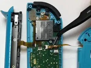
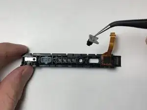
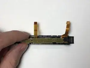
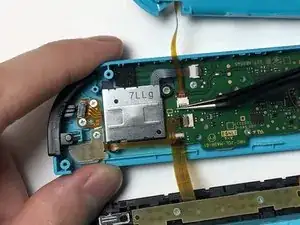
    • Usa un cacciavite a croce Phillips #000 per svitare le due viti da 3 mm al centro della PCB.

    • Rimuovi la PCB dalla guida di carica.

  9. WnUkJLfE5gv3kLnP
    WnUkJLfE5gv3kLnP
    jF6vIQxDKfgKrLjP
    JlIPTR4kttFVRTRr
    • Rimuovi i tasti SL, SR e sync dalla guida di carica.

    If the new charging rail does not have the syncing led extenders, you can take them out and transfer them as well.

    Kallon Lewallen -

  10. H5fVSHLQAwwLxSTu
    H5fVSHLQAwwLxSTu
    hhOVYQuYqqZedVtL
    WVskUurKVJonrGqL
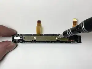
    • Posiziona i tasti SL, SR e sync nella nuova guida di carica e assicurati che le alette sui tasti SL e SR si infilino nelle rispettive rientranze.

    • Appoggia la PCB sui tasti e fissala in posizione usando le due viti a croce Phillips #000 dorate da 3 mm.

    • Potenziali danni per il dispositivo. Se i tasti non sono posizionati correttamente nella guida di carica, avvitare la PCB la farà piegare.

  11. OvLGhdENXXGC1OTP
    OvLGhdENXXGC1OTP
    tTZHSKem5HRdWqAs
    • Allinea la guida di carica con i due distanziali sulla copertura posteriore.

    • Fissa la guida alla copertura posteriore usando le due viti a croce Phillips#000 da 2 mm.

    There’s only one Phillips screw, the upper one, as removed in step 7.

    Guy Bolton King -

  12. VuYeVdYXdEvPnCWy
    VuYeVdYXdEvPnCWy
    VtI1qQ3cKR1UV1FJ
    CapKl3TBwicMvAtH
    • Usa le pinzette per infilare i cavi a nastro della guida di carica nei connettori ZIF sulla scheda madre.

    • Premi i ganci di entrambi i connettori ZIF per fissare i cavi a nastro in posizione.

    Had a pretty hard time reconnecting this one, ZIF connector opened back up quite a few times. So make sure not to put too much strain on the cable

    Mart -

    Note also that there is no latch on the lower cable.

    Guy Bolton King -

  13. kkfArWquRyX2YqK6
    kkfArWquRyX2YqK6
    xqQ1wq2npYGA6yom
    • Usa le pinzette per infilare il cavo a nastro del telaio intermedio nel connettore ZIF sulla scheda madre, con i contatti dorati rivolti verso l'alto.

    • Premi il gancio del connettore ZIF per fissare il cavo a nastro in posizione.

  14. RMkiTIs4CRWmWZCO
    RMkiTIs4CRWmWZCO
    vLV4xAnNYtW5AyZU
    • Appoggia il telaio intermedio sulla scheda madre.

    • Usando il cacciavite a croce Phillips #000, avvita le tre viti dorate da 3 mm del telaio intermedio sulla scheda madre.

    • Mentre appoggi il telaio intermedio sulla scheda madre, il tasto dorsale potrebbe liberarsi. Per riattaccare il tasto dorsale, prima infila la molla sul tasto dorsale nella rientranza nella parte in alto a sinistra del Joy-Con, quindi infila la parte destra del tasto dorsale nel Joy-Con.

  15. 4PG1bamjuuPwJPKZ
    4PG1bamjuuPwJPKZ
    CWO4W5DA1CS2oZZq
    • Appoggia la batteria sul telaio intermedio.

    • Usa le pinzette per allineare il connettore della batteria con la sua presa e uno strumento di apertura o uno strumento con un bordo piatto per premerlo nella presa.

  16. FyspATLZlFlKGGT4
    FyspATLZlFlKGGT4
    yLXl6ijUysrZmxQY
    JIgJoDtEoDPZEISs
    • Allinea la guida di carica nella rientranza sulla parte sinistra del Joy-Con.

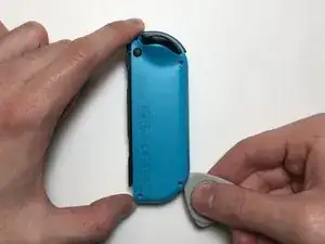
    • Applica una pressione su entrambi i lati del Joy-Con finché le due metà non scattano insieme.

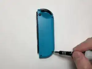
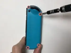
    • Avvita le quattro viti Tri-Point da 6 mm sul retro del Joy-Con.

Peter Lam

Membro da: 20/09/20

1555 Reputazione

14 commenti

I did this and still doesn’t work. I also changed the rail on the console side too. Very carefully of course. Any ideas?

Luis -

Hey Luis,

Can you give me more detail on the problem? Like is the Joy-Con not being detected when it’s plugged in or is it not charging. If possible, can you test the console rail with a working Joy-Con?

If the Joy-Con is not charging, it could also be a battery problem. If you are comfortable with it, I would suggest swapping out the battery with a working one from the other Joy-Con to see if it solves the problem. You should probably attempt this after double-checking the connections for potential tears or if the connectors are too loose in the sockets.

Peter Lam -

Hi, I need help. My left Joy-Con is not charging because of the ZIF connector for the charging rail ribbon has been detached and I have lost it. Is there a way to fix this problem?

Jakkrij Sihanatkathakul -

Honestly, I would recommend replacing the entire Motherboard, unless you can find a trusted repair shop to solder it on.

I damaged the ZIF connector for the battery on my Switch. It works with some pressure and perfect alignment, but I've had issues ever since I damaged it during repairs :/

I'm going to swap it with a functional motherboard, I would advise you do the same.

Yakarot Sennin -

Hello need a little help. the ribbon cable will not stay connected. and it will not charger. Any thing will help.

Matthew Molt -

I damaged my joy con and the lower ribbon wire that connects to the battery has burned out. Is there anyway I can get another set of wires or what not?

Alberto huntington -

Hi There, i trust a bad guide not from here, and seemed to have broke the charging ribbon attachment area. Any way to fix it?

in this guide, it would be step 6, second image. the black part that wraps around the ribbon when it is attached is ripped in half. Some other youtuber said to detach the latch from the front, which i tried. but it was actually in the rear. because he didn't show the step clearly, figured it was that. As i've seen other laptop ribbon latches are similar, pull the thing out, and it pops out. in this case, that was a ribbon connector, and the latch is a flip latch from the rear...

hope you can help. thanks.

Alex -

What if the charging rail is totally broken off? Like, it was pushed off the counter by a small child and the charging rain is totally torn off from the controller

Allie Diane -

If both ribbon cables are completely severed on the rail then you would probably have to also buy a SL/SR PCB replacement. The process would still be the same just use the new SL/SR PCB and make sure that the PCB is for the correct joycon. If you want to find it, you can search for SL SR flex cable or sometimes they are also sold with a new charging rail.

Peter Lam -

I forgot to mention if you broke the peg on the back shell then you may need to replace the back shell. Alternatively, you can try to glue it back together, but if you do, you should check if it can withstand a bit of pressure.

Peter Lam -

Hello. I changed the charging rail and the sr/sl board but my controller won’t connect to my switch. I’ve also swapped the charging rail again to see if that’s the issue and not it won’t charge. The ribbon is in damaged so I’m confused

XxDemon:3 -

Hi I need someones help with my right joy con stick's charging rail. It is charging alright but it's not connecting to my switch in hand-held mode. Is it possible that somebody could post a tutorial like this but for the right joy con? It will really help me a bunch. Thanks.

Toasty -

I would also like this tutorial but for the Right Joy Con. I would've assumed they are similar, but since the guides are labelled very specifically per side, I'd rather not risk it.

My Right Joy Con is not recognised by the Switch, wirelessly or when attached. As a result it doesn't charge, and so It's now off permanently :(

PuyoBop -

Is there a video of this guide?

Liran Belzer -