Introduzione
Dopo un uso prolungato, gli interruttori dei trigger possono diventare meno reattivi anche se gli interruttori non sono danneggiati. Questa guida illustrerà lo smontaggio, la sostituzione e il rimontaggio del controller per sostituire questi interruttori.
-
-
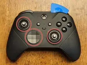
Differisce leggermente rispetto al modello precedente, la placca frontale ha bisogno di essere rimossa prima di ogni altra cosa. Inizia rimuovendo il tappino del joystick e la cover del d-pad.
-
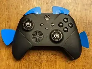
Una volta rimossi, devi iniziare a lavoraci con un attrezzo di apertura(Opening tool) assieme ai plettri intorno alla placca frontale iniziando in alto a sinistra o in alto a destra.
-
Lavora lentamente intorno la placca frontale per allentare le clip, usando principalmente l'attrezzo di apertura in plastica(Opening tool) per evitare ogni tipo di danno alla placca frontale & ai componenti interni.
-
-
-
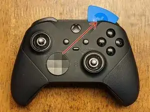
Questa è l'unica parte sulla rimozione della placca frontale nella quale suggerirei di usare lo spudger di metallo perché avrai bisogno di fare maggiore leva per allentare l'adesivo che tiene la placca frontale in posizione.
-
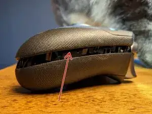
Inserisci lo spudger di metallo nell'area indicata nell'immagine, solamente di quanto ne hai bisogno per far leva verso l'alto nel rimovere la placca frontale. Lavora cautamente e lentamente dato che durante questo passaggio potresti facilmente danneggiare le componenti.
-
L'adesivo può trovarsi in due posti e per questo non sigillare il dispositivo nuovamente insieme per i requisiti IP-67/68, non è necessario sostituirlo.
-
-
-
I joystick sono avvitati sull'asta dei potenziometri e avrai bisogno di un po' di convinzione nel rimuoverli. Essi devono essere girati in senso anti-orario per essere rimossi usando uno dei seguenti metodi:
-
Metodo 1: Utilizzanto il tappino del joystick- Prova questo metodo per prima dato che è meno probabile danneggiare il dispositivo. Inserisci uno dei tappini del joystick e prova a girarlo a mano. Se dovessero essere troppo stretti, procedi con il secondo metodo.
-
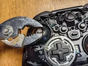
Metodo 2: Usando le pinze - Usando la minor forza possibile che possa prevenire lo scivolamento della pinza, afferra il joystick vicino alla base, dove il pezzo ha una "superficie piana" alla quale le pinze possono far presa. Una volta che si sono allentate, torna ad utilizzare il metodo 1 e continua la procedura di rimozione.
-
-
-
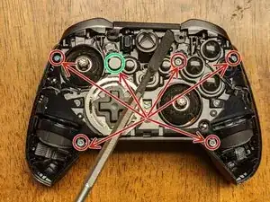
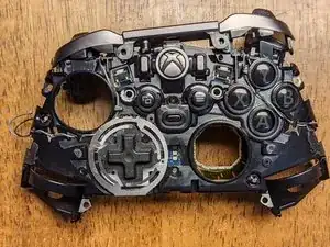
Rimovi le sei viti T-8 di sicurezza che tengono insieme in fronte e il retro del controller insieme. Nota: uno (evidenziate in verde) è coperto dal un/una pasta/adesivo bianco/a che si sbriciola quando rimossa/o; Questo ti fa sapere se qualcun altro in precedenza ha smontato il tuo dispositivo.
-
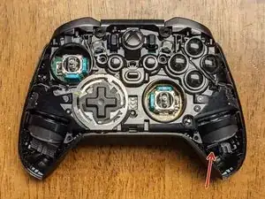
Una volta che le viti sono state rimosse, puoi inserire uno spudger sotto il motore di vibrazione dandogli una piccola leva per separare il fronte dal retro del dispositivo.
-
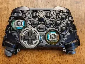
La terza immagine mostra l'assemblaggio frontale rimosso dalle scocca posteriore.
-
-
-
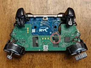
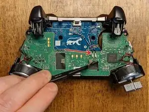
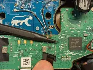
Inizia togliendo il nastro adesivo( delle pinzette potrebbero aiutare) che copre la connessione sulla scheda verde.
-
Mentre tieni il nastro adesivo via, inserisci la punta dello spudger sotto il connettore, facendo pressione verso l'alto con lo spudger da sotto dovrebbe essere sufficiente per rilasciarli dalla scheda.
-
-
-
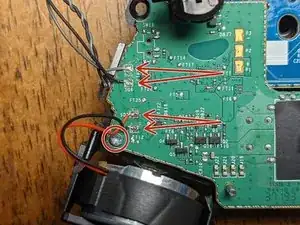
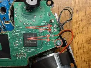
I fili devono essere dissaldati dalla scheda, e saranno sostituiti successivamente nel riassemblaggio.
-
Nota: ogni paio di fili ha il cavo nero saldato nella porzione inferiore; tienilo a mente per il rimontaggio se le immagini di questa guida non saranno vicine.
-
Nota: Potrebbe non essere necessario dissaldarli, dipende da ciò a cui devi accedere nel controller (grazie @bikemerlin per l'idea), però, data la fragilità della saldatura, si consiglia di rimuoverli per evitare danni.
-
Qualche punto di saldatura ha bisogno di una temperatura molto alta per essere dissaldato. Ho impostato la mia saldatrice a 450 C, tuttavia potresti essere in grado di rimuoverla ad una temperatura minore.
-
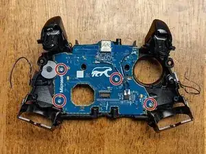
Rimuovi le due viti T-6 dalla scheda vicine ai motori di vibrazione.
-
-
-
Inizia rimuovendo la scheda madre facendola scivolare lungo i pin (come mostrato nell'immagine). Il lato sinistro deve essere alzato fuori dai pin e la scheda deve ruotata in senso anti-orario ad un angolo leggero prima di farla scivolare lungo la distanza rimanente per farla uscire dal pin destro(più lungo).
-
I pulsanti trigger fletteranno un po', questo ti permetterà di avere un po' di spazio in più per la scheda. Come in qualsiasi altro passaggio in questa guida, fai attenzione e sii paziente per prevenire danni a qualsiasi componente.
-
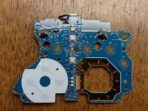
Una volta che la scheda madre è stata rimossa, potresti aver già notato che il jack per le cuffie si è spostato o è caduto. Se non è successo, rimuovilo dalla scheda adesso.
-
-
-
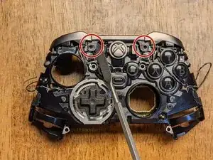
Ci sono due linguette che tengono il fermo per la barra in posizione. Sganciale gentilmente con uno spudger e scivoleranno in alto attraverso la loro stessa tensione. Nota: Il fermo molto probabilmente rimarrà attaccato al assemblaggio del bumper, ma deve essere rimosso prima di procedere al passaggio successivo.
-
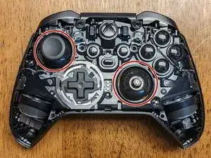
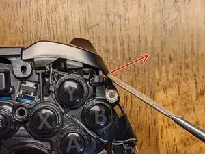
Una volta che il fermo è stato rilasciato, usa nuovamente lo spudger per far leva gentilmente sui pulsanti verso l'alto e verso l'esterno( nella direzione delle frecce nell'immagine) che verranno rilasciate da un'altra clip. Fallo su entrambi i lati.
-
-
-
Rimuovi le quattro viti T-6 che tengono la scheda secondaria del controller al telaio. Tieni a mente che questa scheda tiene tutti il pulsanti rimanenti in posizione, quindi fai attenzione a non perderne nessun mentre la rimuovi.
-
Nota: Tutti i pulsanti hanno delle clip che li circondano che prevengono l'installazione degli stessi in una posizione errata; Fai attenzione a non forzarli in un'altra posizione quando riassemblerai il dispositivo.
-
Quando rimonterai , non forzare nulla in posizione questo indica che qualcosa non è stata installata correttamente.
-
Questo è tutto! Spero che questa guida ti abbia aiutato ad accedere ad ogni componente che ha bisogno di una sostituzione.
-
-
-
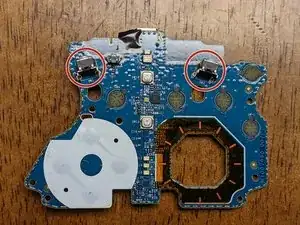
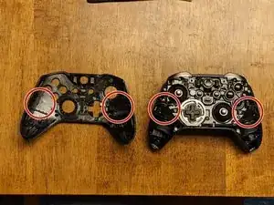
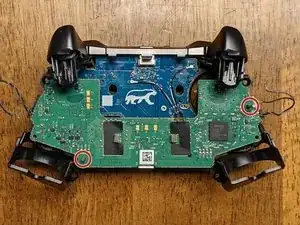
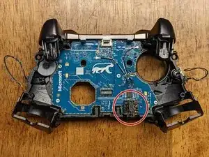
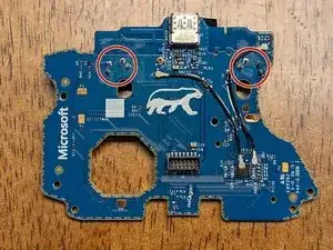
Le aree cerchiate in rosso nell'immagine indicano gli interruttori e i loro connettori che dovranno essere dissaldati e sostituiti.
-
Se non doveste aver acceso ad un saldatore ad aria, sarà molto più facile tagliare i vecchi pulsanti in pezzi. Fai attenzione a lasciare il più possibile che puoi dei pin per avere qualcosa da tirare durante la rimozione
-
Gli interruttori sono sagomanti quindi devono essere spinti con una moderata quantità di forza; questo è quello che rende questa rimozione difficile.
-
-
-
Inserisci la punta del saldatore dentro il foro e utilizza la polpetta dissaldante dall'altra parte per rimuovere tutte le saldature.
-
Sfortunatamente, Non ho fatto foto di questo processo, comunque , questo è il passaggio dove la polpetta dissaldante diventa necessaria. I nuovi pulsanti hanno bisogno di un ampio spazio per essere inseriti nei fori, devi far in modo che non rimanga della saldatura.
-
-
-
Una volta che i pulsanti hanno abbastanza spazio per essere inseriti, si terranno da soli in posizione perché hanno abbastanza tensione verso l'esterno per farlo.
-
Aggiungi nuove saldature alle connessioni.
-
-
-
Questo passaggio dipende dai pulsanti di ricambio che hai comprato, potrebbe essere necessario limare il braccio sotto che spinge sul pulsante. Questa è la parte del bumper che estende verso il basso e preme fisicamente il pulsante stesso.
-
Per me è stato necessario dato che avevo dei pulsanti avanzati dell'Xbox 360 che sembrano più tattili e durevoli di quelli dell'Xbox One.
-
Per riassemblare il tuo controller, segui questa guida in ordine inverso.

Un commento
decent guide, except for step 13 imo. these switches are dirt cheap, i can't see it being a good idea to modify the part of the bumper instead of ordering the proper switch.
bmx6454 -
Starting center to sides from top, then center to sides from bottom worked for me.
Robert Cole -