Introduzione

Se il tuo tablet non si carica e hai verificato che il tuo caricatore funziona correttamente, potresti doverne sostituire la porta di carica.

  1. GZ2Pki1FpHlvCO3S
    GZ2Pki1FpHlvCO3S
    5VJRorbfRR23MCuC
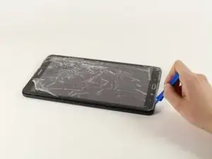
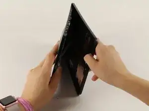
    • Appoggia il dispositivo con lo schermo rivolto verso l'alto.

    • Inizia vicino ad uno dei bordi curvi del dispositivo(usa la seconda immagine come esempio).

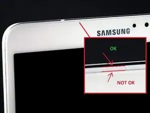
    • Infila uno strumento di apertura in plastica tra la copertura posteriore e quella anteriore.

    • Se uno strumento di apertura in plastica non funziona, prova con uno spudger in metallo, ma potresti danneggiare la plastica sul dispositivo.

    • Ricordati di rimuovere la scheda micro SD (se inserita) prima di iniziare.

    AWESOME!! I was trying to open it from the “NOT OK” place and you saved me to broken the screen… thanks!!

    David Leiva -

    No problem, enjoy.

    Roger L. Ortiz -

    Felt it was easier for me to do it from the middles out.

    Tanin Garcia -

    @rogerlortiz You two seem to be miscommunicating. The author points out the location between the digitizer and frame in which to place a tool. While @Tanin Garcia, whom no longer seems to be member, was pointing out where along the edge from corner to corner it was best to start the separating process.

    B. A. Computer Services -

    Important: the display is sourrounded with a plastic frame. You need to get beween this frame an the backcover (not directly at glass edge as I tried it first and almost broke the glass). Get a closeup picture of it to clarify.

    Oliver Dawid -

    wer lesen kann, ist klar im Vorteil - ich hab die SD-Karte drin gelassen. Hat aber funktioniert…

    Thomas Wolter -

    Don’t use a very small flathead screwdriver as a spudger. Just shattered the screen :(

    nikvoss -

    Yes, shattered the screen. To the garbage, it goes. A little knowledge is a dangerous thing. This a repair better suited for a professional repair! Thanks for helping me make the decision to get another one!

    vancega -

  2. FEt6AIIjfR5mPXQH
    FEt6AIIjfR5mPXQH
    SOQODCRyQZlwVvj1
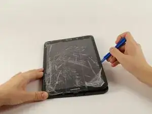
    • Una volta che lo strumento di apertura in plastica è stato infilato, usalo per fare leva lungo i bordi del dispositivo per separare la copertura posteriore.

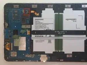
    • Rimuovi la copertura posteriore dal dispositivo.

    • La copertura posteriore emetterà qualche crepitio mentre viene rimossa dal dispositivo.

  3. aKoSIwKnMC1lAyYP
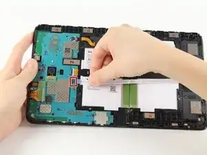
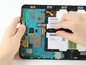
    • Rimuovi la protezione adesiva e ruota verso l'alto l'aletta di bloccaggio sul connettore ZIF della batteria.

    • Sfila il cavo a nastro arancio della batteria dalla sua presa.

    BEWARE!!! later on Samsung tablets the tab holding the main cable (marked “MAIN”) breaks as soon as you attempt to lift the tab to remove the ribbon! I reckon Samsung designed this breakabloe tab to not only avoid the warranty, but the render the tablet useless!

    graham chapman -

    Happened to me also, in order to replace that broken tab, do you think it will be necessary to replace the motherboard? I highly doubt we can find the parts to fix (replace) the flip-tab.

    jeanuhlik -

    I also had this problem, the connector broke, even if i was very careful, i still can use the tablet, i pushed the “main” cable in place and used a little bit of hotmelt glue to hold it in place.

    Yannick -

    I tried using aluminum foil to make the connection but it didn’t help at all, how did you attach it with the glue gun???

    jeanuhlik -

    LOOK what I found!!! its the replacement for the connector we broke!!!https://www.parts4repair.com/samsung-gal...

    jeanuhlik -

    i just wonder how u gonna solder this tiny thingie

    Mike Muley -

    I wish I had read this thread before I removed the cable and broke the connector. Unfortunately I have not been able to reattach the cable and my tablet is dead.

    If there is no way to remove this cable, why is this fix even posted here? I find this exceptionally uncool!

    Derek N. Eder -

    Whoever broke the connector was trying to open it the wrong way. I have oil spilled in mine after I replaced my screen and digitizer together if you only replace the screen it is more difficult. I say changing both together is simpler. And I will share a pic either way I just might mess up MY connector. To be continued

    909 -

  4. 1OplFVIHHB6iE5cO
    1OplFVIHHB6iE5cO
    rwOOcqLwpiM2JFMo
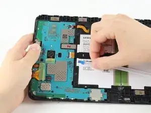
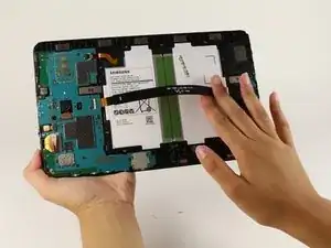
    • Rimuovi la protezione adesiva, solleva l'aletta di bloccaggio e sfila il cavo a nastro bianco dello speaker dalla sua presa.

  5. 1uZdAEXRWTnJfwkc
    1uZdAEXRWTnJfwkc
    QNlFwvR4JP4LMckg
    vBRRQDtXcrOZQgDV
    • Solleva l'aletta di bloccaggio e sfila il cavo a nastro nero dello schermo.

    It's possible to replace only the lcd cable connector? Ist das möglich nur das Flachbandkabel zu tauschen?

    Lima -

  6. O4bvieDFdNTtVvWS
    O4bvieDFdNTtVvWS
    pSQTogUPIWyaBqa3
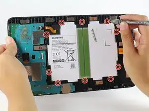
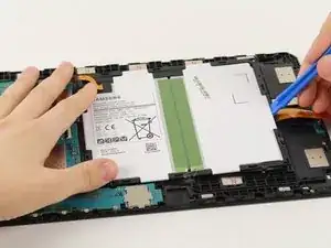
    • Usa un cacciavite a croce Phillips #000 per svitare le dieci viti da 4 mm attorno alla batteria.

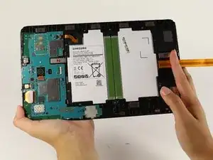
    • Infila uno strumento di apertura in plastica sotto il bordo inferiore della batteria vicino allo speaker e sollevala.

    • Il grande rettangolo bianco e nero è l'intera batteria. Stai attento a non forarla.

  7. fPglWd16CqrfTnPk
    fPglWd16CqrfTnPk
    Ixaqq2Rd5qpRFqsy
    xE4TWX2YDWswXU6Z
    • Ruota verso l'alto le due alette di bloccaggio sui connettori ZIF con uno strumento di apertura in plastica.

    • Sfila i cavi a nastro arancio dalle loro prese.

    • Rimuovi la fotocamera anteriore.

    This step omits the disconnection of the battery from the motherboard , which is shown disconnected in this picture but was connected in the previous step

    Christopher Ford -

    Thanks for bringing this to our attention. We added the relevant battery disconnection steps—hope this helps!

    Kristen Gismondi -

    If the model you are working on is the T585 you will need to carefully pry up the blue antennae cable and disconnect the sim card slot from the motherboard.

    Brendon Gould -

  8. ZeXlPco1GFY2fcas
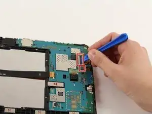
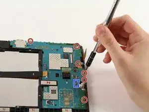
    • Scollega la presa jack dalla scheda madre.

    • Usa un cacciavite a croce Phillips #000 per svitare le sei viti da 4 mm.

    die ganze Platine musste ich gar nicht ausbauen. Ich konnte die Kopfhörerbuchse vorsichtig mit einem kleinen flachen Schrubendreher lösen.

    Thomas Wolter -

  9. sR1EQqLISYUKoWBI
    sR1EQqLISYUKoWBI
    ZWuKRRPlJL6FGDYS
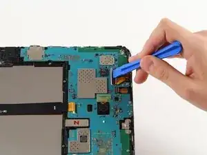
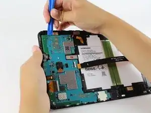
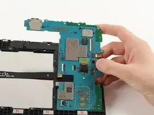
    • Infila lo strumento di apertura in plastica sotto la scheda madre, sollevala e rimuovila dal tablet.

    • Stai attento a non far impigliare i connettori.

    • Rimuovi il supporto in metallo che stava sotto la porta di carica e mettila da parte.

    Replacing the broken screen, I stupidly unhooked the LCD with a metal screwdriver. It makes the sound of coming on but no picture. Is that the motherboard?

    MARGARET -

    I replaced screen once before and had no problem except using a screwdriver this time.

    MARGARET -

    I have tab a charging and show on screen but not starting at all motherboard water damage I clean all there any way make it start by motherboard with out power button

    waleed nawzad -

    TIP: Before next step (or sooner), cover cracked/broken glass with transparent tape to avoid (I didn't) or minimize small shards of glass falling into work area and onto your clothing.

    Bruce Grant -

  10. C2I1OYnhIZjMNQrG
    • Appoggia una treccia dissaldante su uno dei quattro fori sul lato superiore della scheda madre.

    • Appoggia il saldatore sopra la treccia sulla parte argentata del foro per rimuovere la saldatura. Se è la prima volta, abbiamo una guida per aiutarti.

    • Se la treccia dissaldante si riempie di saldatura e non ne assorbe più, cambia parte della treccia che stai usando.

    • Il saldatore sarà molto caldo e può bruciare sia le tue mani che il dispositivo.

    Please be sure not to hold the soldering iron by the hot end as shown in the picture

    Michael Wilkosz -

  11. ePb64x1sc1bHDgPZ
    • Ripeti il passo precedente per gli altri tre fori.

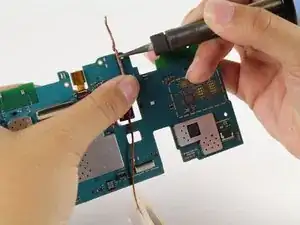
    • Solleva la porta di carica in metallo dalla scheda madre.

Conclusione

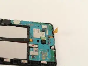
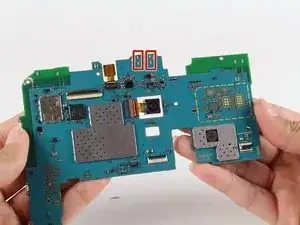
Per rimontare il dispositivo, posiziona la nuova porta in metallo dove era l'originale e saldala sul lato corretto della scheda madre nei quattro fori appositi.

Isabella Li

Membro da: 02/10/17

2358 Reputazione

13 commenti

It is impossible to unmount the old damaged USB-Interface this way. Beside the four solder-points ist is also soldered to 5 extremely small points on the motherboards opposite side. These are SMD-mounted contacts and in my case trying to unsolder them damaged the motherbords layout.

Lutz Christoph -

I was able to desolder it with a hot air rework station + soldering iron without damaging the pcb then using a wick cut at an angle + the heat gun to clean the mounting holes you must clean then fully so the new part will mount flush.

Also take care with resoldering the new connector not to bridge the pins on the usb port.

cusbrar2 -

what is the model of USB connector here? I would like to buy in advance before opening

Алексей Хейдоров -

These instructions are really incomplete. In addition to the 4 through-hole points mentioned, there are also 2 large ground pads under the connector, and 7 tiny surface-mount pins on the back. Removing this port pretty much requires low-temp (chip-quick) solder or a hot-air rework station. Soldering it back on with only an iron proved quite difficult - hot-air rework station highly recommended. This took me about an hour, and I’ve been soldering (hobby mostly) for the better part of 30 years.

Also, there’s no reason to remove the battery to change the charging port. The motherboard can be removed without removing the battery. And really, the cameras should be disconnected too, rather than leaving them dangling by their ribbon cables.

Nathan Lewis -

Where can you buy the exact replacement USB port

yafecker -

Please tell us what region you’re in and someone might be able to help with a relevant suggestion.

Philip Le Riche -

Sucessfully completed. More Flex cables to disconnect, but thats straightforward. Replacement part from ebay. Unsolder and soldering are complicated even with professionell hot air station, microscope etc. But now it works

fox_alpha_fox -

Just a quick question. Does the USB port have to be fully removed? If the unit is not charging isn’t it more likely that one of the solder connections is simply broken?

Cheers,

A

andrewscline -

What type of solder should be used to re-affix the new charging port?

Jim Barber -

Lead-free solder paste. Small amounts are sold in syringes, eBay is a good source

Chris Halliwell -

The circuit board will need some heat prior to using a hot-air solder station. You will need to remove both cameras before subjecting to a pre-heat. Pre-heat to between 150 and 200c then apply enough heat to reflow the solder joints. A pair of tweezers will help remove the old USB socket. Once removed desolder the throu-holes and clean the surface mount pads. Apply small amounts of solder paste on the solder pads and fill the trou-holes, before placing the new USB socket . The PCB will need pre-heating again before finally using the hot-air solder gun to flow the solder joints. Check SMD pads and throu-holes have all flowed properly.

Chris Halliwell -

Chris Halliwell knows what they are doing. If you don't have a hot air station, decent soldering station and surface mount soldering experience plus the sundries ie solder paste, good tweezers, good lighting, magnify glass as a minimum then don't even try.

Surface Mount soldering around temperature sensitive components is a risky game unless you are aware of the processes involved. Even then it only takes a few extra degrees in temperature to melt and fry surrounding part's.

rj young -

This i see is not for the faint of heart.

Lew Buckles -