Introduzione
Segui questa guida per rimuovere o sostituire il pulsante accensione del tuo iPhone 7. Riguarda solo il pulsante fisico e non la parte elettronica sottostante.
Se devi sostituire il cavo volume e il pulsante accensione, segui questa guida.
Strumenti
-
-
Spegni il tuo iPhone prima di cominciare a smontarlo.
-
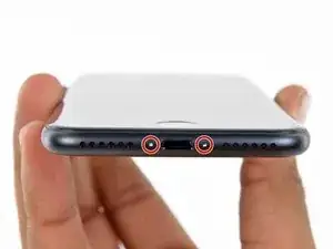
Rimuovi le due viti pentalobe da 3,4 mm nella parte inferiore del tuo iPhone.
-
-
-
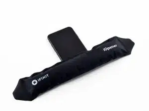
Usa un asciugacapelli o prepara un iOpener e applica calore per circa un minuto per ammorbidire l'adesivo sottostante.
-
-
-
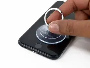
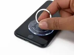
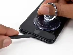
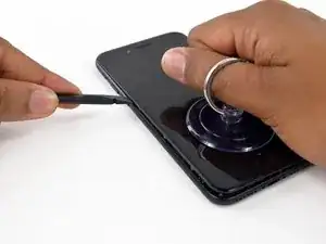
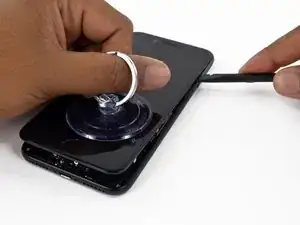
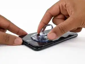
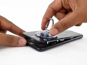
Tira la ventosa fino a creare una piccola fessura tra il gruppo display e il case posteriore.
-
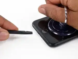
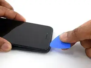
Inserisci l'estremità piatta di uno spudger nella fessura.
-
-
-
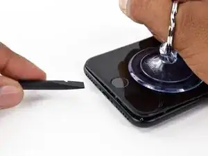
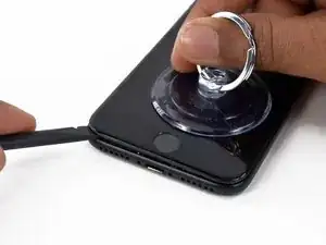
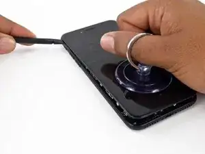
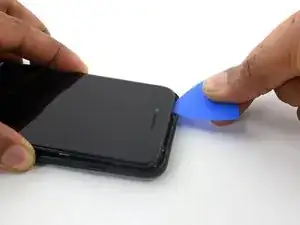
Fai scorrere lo spudger verso sinistra lungo il lato inferiore dell'iPhone.
-
Ruota lo spudger per allargare la fessura tra il display e il case posteriore.
-
-
-
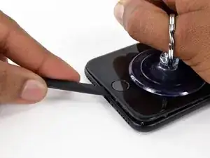
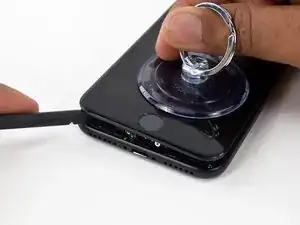
Fai scorrere lo spudger lungo il lato sinistro dell'iPhone, iniziando dalla parte inferiore e spostandoti verso i pulsanti del controllo volume e l'interruttore della modalità silenziosa.
-
-
-
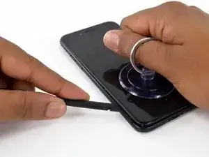
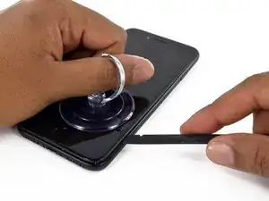
Inserisci l'estremità piatta di uno spudger nell'angolo inferiore destro del dispositivo.
-
Ruota lo spudger per allargare la fessura tra il gruppo display e il case posteriore.
-
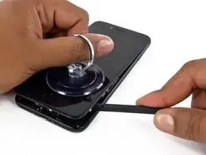
Fai scorrere l'estremità piatta dello spudger sul lato destro del telefono per rompere l'adesivo che tiene in posizione il display.
-
-
-
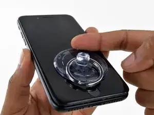
Solleva la piccola appendice della ventosa per rimuovere lo strumento dal pannello anteriore.
-
-
-
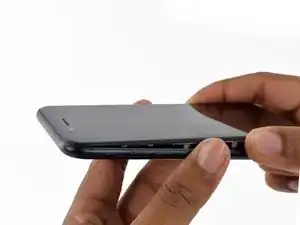
Fai scorrere uno strumento di apertura lungo il lato superiore dell'iPhone, tra il case posteriore e il pannello anteriore, per rompere la parte restante dell'adesivo che tiene in posizione lo schermo.
-
-
-
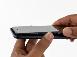
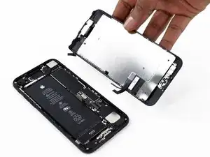
Tira lievemente in orizzontale il gruppo display per allontanarlo dalla parte superiore del telefono per scollegare le clip che tengono bloccato lo schermo al case posteriore.
-
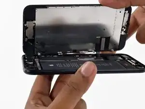
Apri l'iPhone sollevando il display dal lato destro, come se fosse la copertina posteriore di un libro.
-
-
-
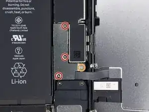
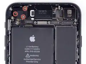
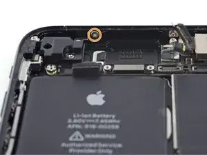
Rimuovi le seguenti viti con testa tri-wing Y000 dalla staffa inferiore del connettore:
-
Tre viti da 1,2 mm
-
Una vite da 2,4 mm
-
-
-
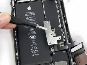
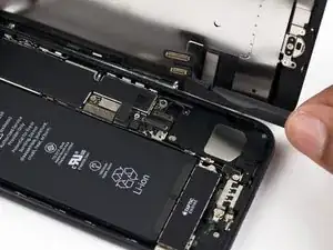
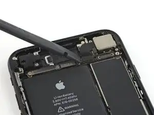
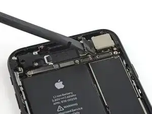
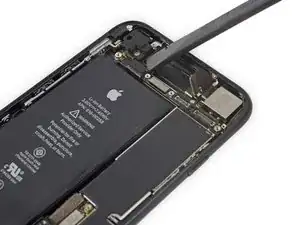
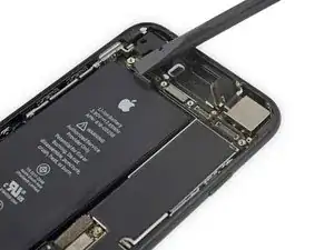
Usa l'estremità a punta di uno spudger per sollevare il connettore della batteria dal suo zoccolino sulla scheda logica.
-
-
-
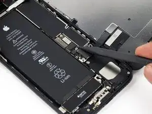
In questo passo, accertati che la batteria sia scollegata quando disconnetti o riconnetti i cavi.
-
Usa l'estremità piatta di uno spudger o un'unghia per staccare i due connettori inferiori del display sollevandoli verso l'alto dai loro zoccolini sulla scheda logica.
-
-
-
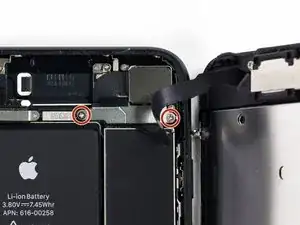
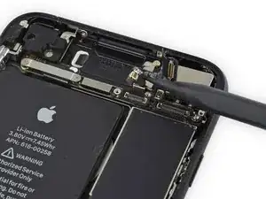
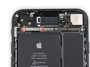
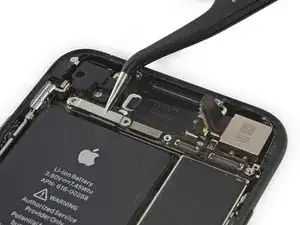
Rimuovi le due viti Phillips da 1,3 mm che fissano la staffa sopra il connettore del gruppo sensore del pannello frontale.
-
-
-
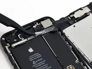
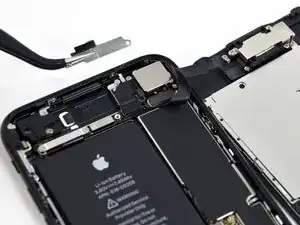
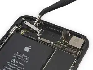
Stacca il connettore del gruppo sensore del pannello frontale dal suo zoccolino sulla scheda logica.
-
-
-
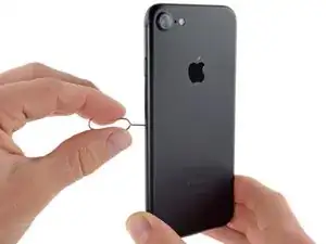
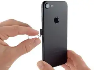
Inserisci uno strumento per l'estrazione della scheda SIM o una graffetta nel piccolo foro nel vassoio della scheda SIM.
-
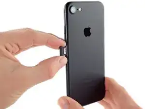
Premi per estrarre il vassoio.
-
Rimuovi il vassoio della scheda SIM dall'iPhone.
-
-
-
Usa l'estremità piatta di uno spudger per staccare il connettore della fotocamera posteriore.
-
-
-
Rimuovi le seguenti viti Phillips che fissano la staffa della fotocamera posteriore al case posteriore:
-
Una vite da 1,3 mm
-
Una vite da 2,5 mm
-
-
-
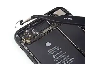
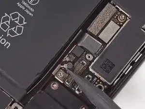
Usa l'estremità a punta di uno spudger per far leva e staccare il connettore del cavo del bus dell'antenna, appena a sinistra del modulo della fotocamera posteriore.
-
-
-
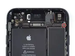
Rimuovi le quattro viti a croce Phillips di fissaggio dell'antenna Wi-Fi:
-
Tre viti da 1,2 mm
-
Una vite da 1,7 mm
-
-
-
Rimuovi il distanziale a vite da 2,2 mm dalla staffa di terra.
-
In caso di emergenza, può bastare un piccolo cacciavite a taglio, ma è necessaria un'estrema cautela per evitare che scivolando possa danneggiare i componenti circostanti.
-
-
-
Usa delle pinzette per piegare delicatamente la staffa di messa a terra della scheda logica in modo che non dia fastidio.
-
-
-
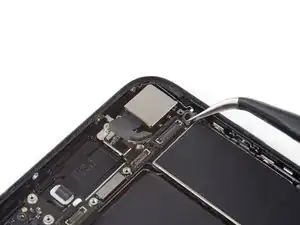
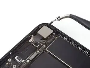
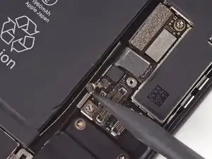
Usa la punta di uno spudger per sollevare i due connettori del cavo dell'antenna dai loro zoccoli sulla scheda logica.
-
-
-
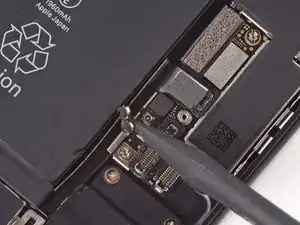
Usa delle pinzette per sfilare delicatamente i cavi dell'antenna dalla staffa in metallo sulla scheda logica.
-
-
-
Usa la punta di uno spudger per spostare il cursore di estrazione della scheda SIM lontano dalla scheda logica.
-
-
-
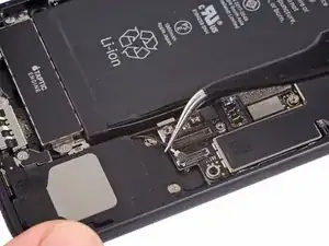
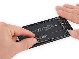
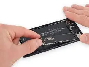
Usa l'estremità piatta di uno spudger per sollevare delicatamente verso l'alto il terminale del connettore della batteria dalla scheda logica.
-
-
-
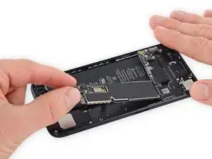
Solleva la parte della scheda logica con il connettore della batteria e tirala verso l'alto e distante dal case posteriore.
-
-
-
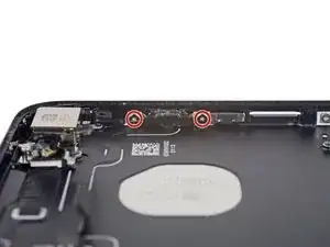
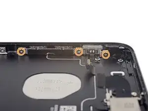
Rimuovi le seguenti viti Phillips:
-
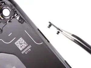
Due viti da 1,9 mm che fissano il pulsante di accensione
-
Tre viti da 2,3 mm che fissano i pulsanti del volume.
-
-
-
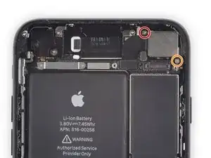
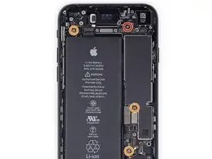
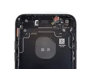
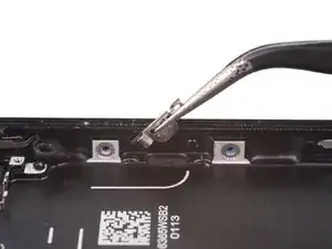
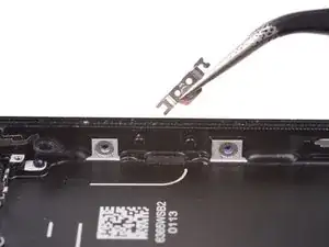
Rimuovi le seguenti viti Phillips da 1,3 mm:
-
Una vite oltre la fotocamera posteriore
-
Una vite sul case posteriore
-
-
-
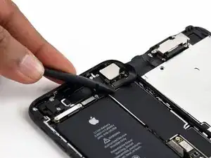
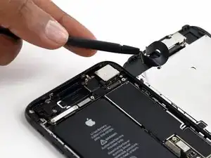
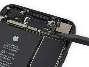
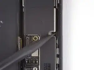
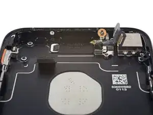
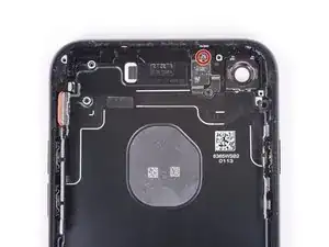
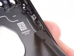
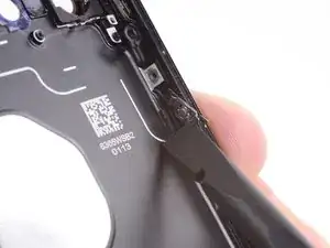
Dall'esterno del telefono, spingi il pulsante hold verso il case posteriore utilizzando la punta di uno spudger.
-
Questa operazione serve a liberare il pulsante hold e la sua guarnizione dal case posteriore.
-
-
-
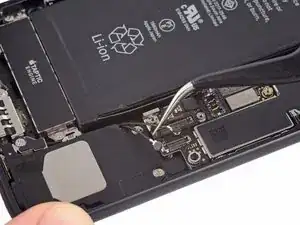
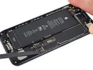
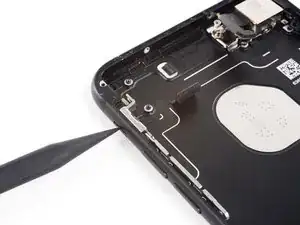
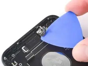
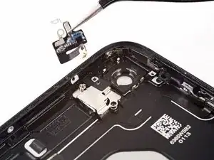
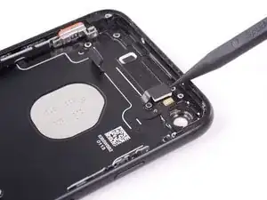
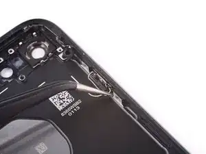
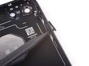
Arrivando dal lato del pulsante di accensione del telefono, usa un plettro di apertura per separare l'adesivo che tiene in posizione del cavo flessibile dell'antenna sul caso posteriore.
-
-
-
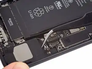
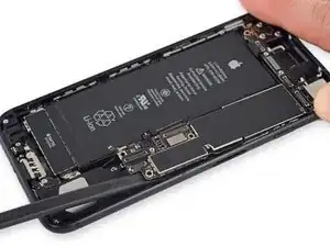
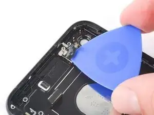
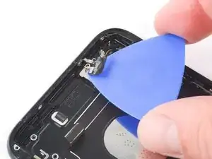
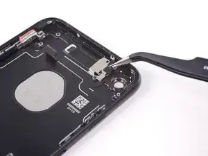
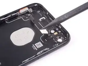
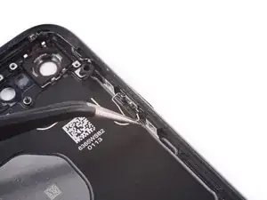
Fai scorrere la punta di uno strumento di apertura sotto il cavo flessibile dell'antenna e verso la parte superiore del telefono per separare l'adesivo rimasto.
-
-
-
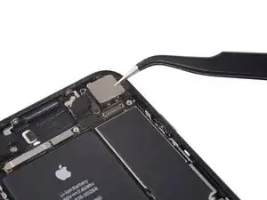
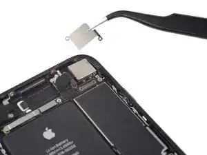
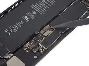
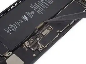
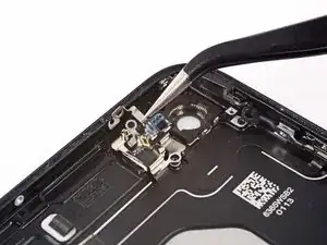
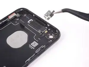
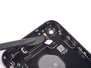
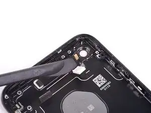
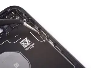
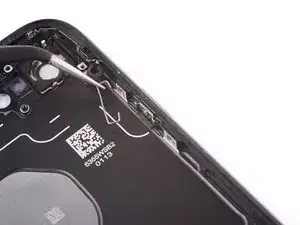
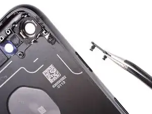
Usa delle pinzette per spostare il cavo flessibile dell'antenna lontano dal bordo del telefono, liberando la staffa dal case posteriore.
-
Rimuovi il cavo flessibile dell'antenna.
-
-
-
Rimuovi i due distanziali a vite da 2,3 mm che fissano la staffa del flash al case posteriore.
-
-
-
Usa la punta di uno spudger per scalzare con delicatezza dal suo alloggiamento il modulo flash.
-
-
-
Usa la lama di uno spudger Halberd per separare l'adesivo che incolla il microfono al case posteriore.
-
-
-
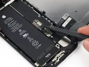
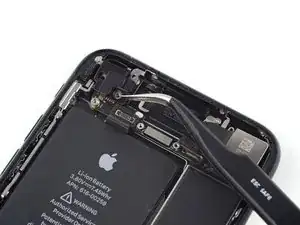
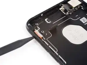
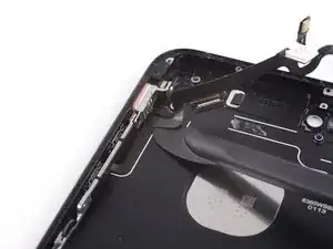
Fai scorrere la lama di un spudger Halberd sotto l'estremità dal lato del pulsante del cavo a piastra per separare il cavo stesso dall'adesivo presente sul case posteriore.
-
Continua a separare l'adesivo spingendo la lama verso la parte superiore del telefono.
-
-
-
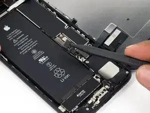
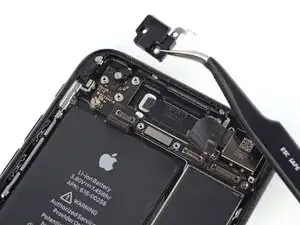
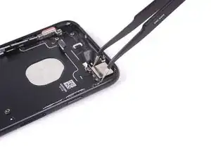
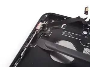
Continua a spingere la lama dello spudger Halberd sotto il cavo dei pulsanti di accensione e controllo volume.
-
-
-
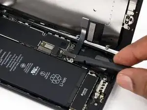
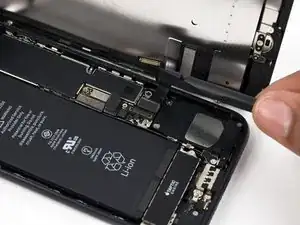
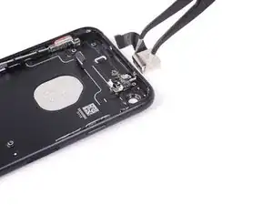
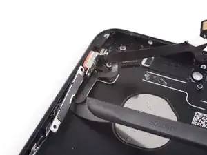
Fai scorrere lo spudger Halberd sotto la parte del controllo volume del cavo a piastra.
-
Fai scorrere delicatamente la lama sotto il cavo, verso la parte inferiore del telefono, per separare l'adesivo rimasto.
-
-
-
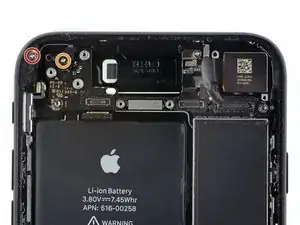
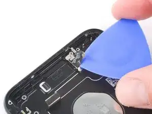
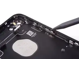
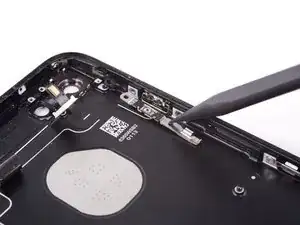
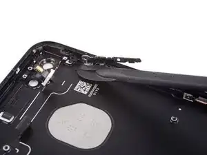
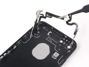
Spingi la clip verso la parte inferiore del telefono e sollevala per staccarla dalla staffa.
-
-
-
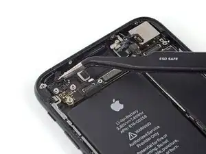
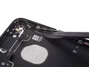
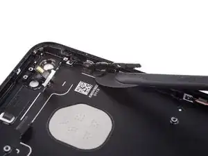
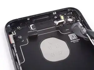
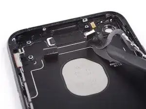
Stacca l'estremità inferiore della staffa del pulsante accensione dal piccolo piolino che la tiene in posizione.
-
-
-
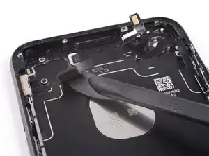
Usa la punta di uno spudger per spingere fuori dal case posteriore la copertura del pulsante home.
-
Rimuovi la copertura del pulsante home.
-

Per rimontare il tuo dispositivo, segui queste istruzioni in ordine inverso.

3 commenti
Alright so quick question…….
the clip shown in step 57 the one that resembles a staple,is this necessary?
Im doing a housing swap for myself and I cannot get these back on going on an hour now my hands are huge so im wondering if everything will be okay if I don’t replace these.(normally if it were another person’s device I would never take a shortcut,Never have and Never will in fact I despise this,but it’s my phone so it’s cool).
thanks
I can't see a response. Are the clips necessary?
It is probably to keep it in place, so I think it’s not necessary but recommended
Can anyone confirm 7/7P's pentalobe screws have a ring of seal near the screw head?
Cooper Chase -
Confirmed, the screws have a black ring seal around the head.
rcheing -
Can’t get the display front
Bernadette Pfeifer -
From personal experience, I highly recommend before doing this procedure or any other, that you do a backup of your phone (preferably local) in case your procedure goes south.
ballina5ny -
I purchased the repair tools with the replacement battery from iFixit. The tools include a screw driver and three heads none were labeled 3.4 mm. I think the one that fit the pentalobe screws was labeled Y000. The guide should identify the screw driver head supplied by the kit not 3.4mm.
Mark Lieberman -
in the iphone 7 replacement battery kit from iFixit, the screwdriver that fits the 3.4 mm pentalobe screws is labeled P2 (and not Y000)
Jan-Tijn Oppermann -
3.4 mm is the height of the screw and is not related to the screw driver code.
Ahmad Vaziri -
the screwdriver PH000 does not work i wasted two screws and now they dont have the 4 cross mark they are now a circle, i buyed it all from Paraguay and it doesnt work, had to assembly back the parts because i got stuck like i mention with some screws, well im just going to send to a professional to install, thanks
Martin Frutos, Nuñez -
The bottom screws are Pentalobe, not Phillips.
Bram Driesen -
Before starting, I would recommend backing up your Iphone’s data just in case.
Jon Moylan -
If you managed to make it to this section, just send the phone into apple for 50 + 6 dollars shipping. The ribbon cables on the screen are designed to break. I can literally twist on the rest of the cable and it won’t fall apart but there is a diagonal section where it snaps. This is the fault of apple and the fault of ifixit for misrepresenting the fragility of the cables.
Ryan Huebert -
Had to reheat it a few times for a minute each with a hairdryer to get the seal to break after pulling and rocking the suction
Cynthia Lamb -
I’m technically challenged. Is there a premier national service who can professionally install a replacement battery got my 7 +?
Richard -
Do the screws come out in total?
YVES THEUGELS -
They may come out or may not. If you loosen as much as you can and they don't come out you should still be able to pry open the bottom. Once you get the screen off you can then push the screws out from the inside.
Anthony Falabella -
Is it the P2 you should use for the bottom??
YVES THEUGELS -
I heated the bottom of the phone with a hairdryer and then used a syringe to put a couple of drops of acetone directly into the bottom two screw holes. I GENTLY pulled on the screen with the suction cup and used the pry tool to GENTLY separate the screen. The sealant is applied around the entire display so be very careful pulling it off so you don’t break the fragile display cables.
Anthony Scaminaci -
At first it was very difficult to open, per instructions. I used a heat/ice pack and nuked it for 1 minute. The pry tool wasn’t working so I carefully used my pocket knife to wedge the cover open. The rest of the procedure went well until I cracked the glass while trying to get the top right corner to pop off. Other than that mistake, all went well. Tip: before setting the new battery, attach the battery connector first and leave enough room for the taptic engine, or better yet, place the taptic engine before adhering the replacement battery. This way you’ll have a small gap between the two, whereas mine barely fit. Good job on hosting the video, Gwendyl.
Klaus Preiss -
I love the fact that the screw bit and shaft are magnetic! I almost lost a screw and found it attached to the magnet.
I used a heat/ice pack and nuked it for 1 minute. At first the display cover was very difficult to open with the pry tool, per instructions. The pry tool wasn’t working so I carefully used the blade of my pocket knife to wedge the cover open. The rest of the procedure went well until I cracked the glass while trying to get the top right corner to pop off. Other than that mistake, all went well. Tip: before setting the new battery, attach the battery connector first and leave enough room for the taptic engine, or better yet, see the taptic engine in place before adhering the replacement battery. This way you’ll have a small gap between the two, whereas mine barely fit because I placed it almost too low.
Good job on hosting the video, Gwendyl.
Klaus Preiss -
I replaced the lightning connector assembly and reassembled. The old one did not 'click' into the cable and had corrosion inside, it needed the cable to be placed in a specific way to charge. The new part - does not recognize that a charger is plugged in at all.
I backtracked the assembly - took it apart, put it back again - and find that every thing on the part works - the mic, speakers, taptic engine.
The original problem with the cable still persists. Any ideas?
H K -