Introduzione
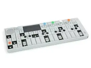
La scheda UI si prende carico delle azioni su manopole e tastiera e si connette all'altoparlante. Se si guasta, il divertimento finisce subito.
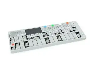
Questa guida mostra come sostituire la scheda UI del tuo OP-1.
Ricambi
-
-
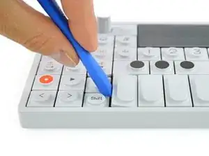
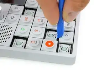
Per i quattro tasti più lunghi della tastiera, si deve intervenire a partire dal lato sinistro.
-
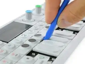
Per staccare gli otto tasti più piccolibisogna iniziare dal basso.
-
-
-
Il meccanismo a pantografo degli otto tasti piccoli impedisce l'accesso alla vite sottostante.
-
Usando di nuovo uno strumento di apertura un plettro, si possono estrarre facilmente questi elementi.
-
-
-
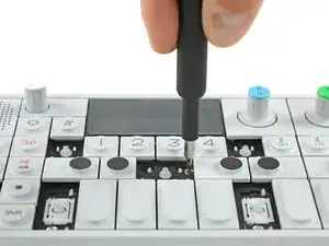
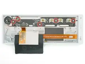
Svita queste 12 viti con un cacciavite a croce Phillips #00.
-
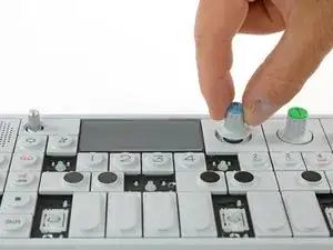
Quindi basta tirar fuori le otto manopole ruotanti e la manopola del volume.
-
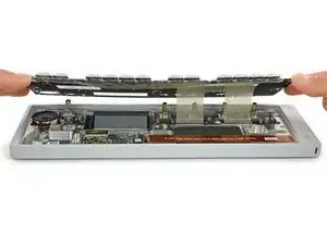
Ora è possibile sollevare lievemente la tastiera e disporla più indietro.
-
-
-
Il display è tenuto in posizione con un adesivo poco tenace. Per liberarlo, aiutati con uno spudger.
-
Accertati di non danneggiare il display quando lo rovesci verso il davanti per accedere alla scheda UI.
-
-
-
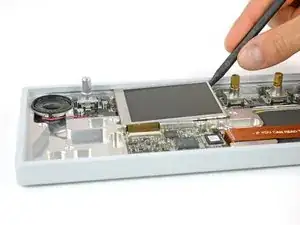
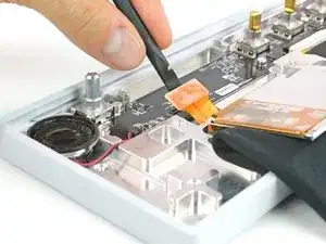
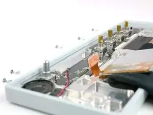
Scollega dalla scheda UI il cavo flessibile DSP.
-
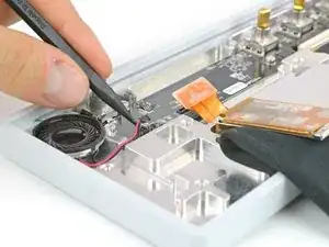
Scollega dalla scheda UI il cavo dell'altoparlante.
-
-
-
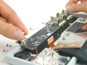
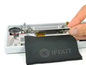
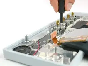
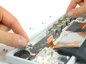
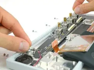
Ora la scheda UI è libera e può essere estratta. Puoi afferrarla per le manopole iniziare a sollevarla parzialmente dal lato destro.
-
Sul lato sinistro, l'altoparlante suo cavo potrebbero interferire se cerchi di tirare la scheda direttamente verso l'alto. Ti basterà spostarla diagonalmente verso destra per poterla estrarre completamente.
-
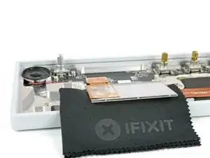

Per rimontare il tuo dispositivo, segui queste istruzioni in ordine inverso.

2 commenti
Can anyone recommend a good adhesive tape to fix the screen in place after doing the repair?
No need to replace the adhesive tape as long as you leave it attached to the op1 or to the back of the display itself. So when you go to put everything back together, slot the display back into place, the adhesive tape that is there should stick very gently and when you go to put the keyboard with the display glass back, everything will be held in place.
Also, this guide skips over detaching the ribbon cables when you are removing the keyboard, the two connectors each have two (2 on each port) very small black colored locking mechanisms on the left and right of the cable's port, using a spudger you can push those locking mechanisms up about 2mm, and the ribbons should detach from the ui board seamlessly allowing you to gently pull them out. When putting it back together, insert the ribbon cable evenly to the new port, and push the locking mechanisms into place (reverse from what you did before).