Introduzione
Prerequisito interno.
-
-
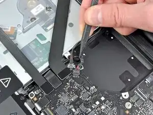
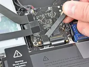
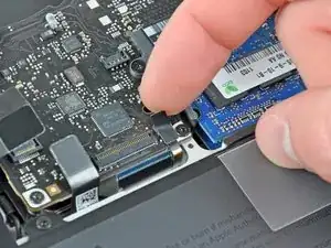
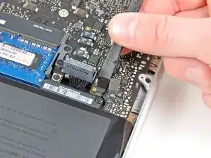
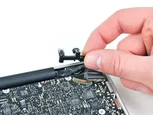
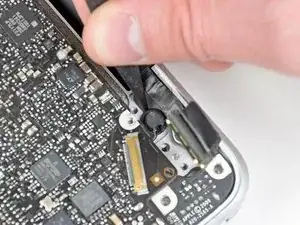
Usa la punta di uno spudger per tirare il cavo dell'altoparlante/subwoofer destro fuori dalla sporgenza di bloccaggio in plastica integrata nella scocca superiore.
-
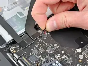
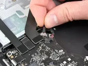
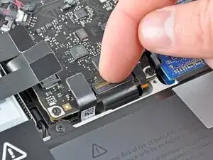
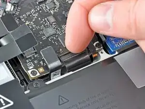
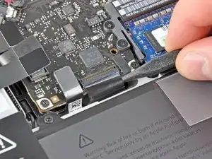
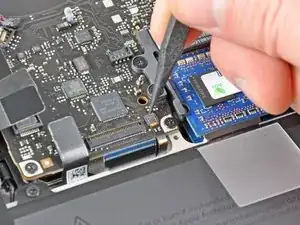
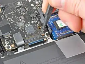
Tira il cavo dello speaker destro verso l'alto per scollegarlo dalla sua presa sulla scheda madre.
-
-
-
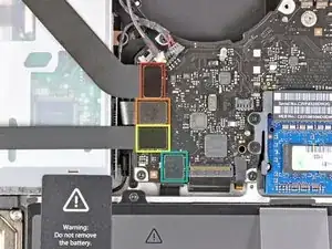
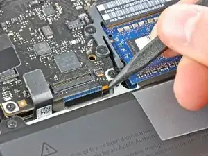
Scollega i seguenti quattro cavi:
-
Cavo AirPort/Bluetooth
-
Cavo lettore CD
-
Cavo disco rigido
-
Cavo trackpad
-
-
-
Usa un'unghia per ruotare verso l'alto l'aletta di bloccaggio sul connettore ZIF del cavo della tastiera.
-
Usa la punta di uno spudger per sfilare il cavo della tastiera dalla sua presa per scollegarlo.
-
-
-
Se presente, rimuovi la piccola striscia di nastro nero che copre la presa del cavo della retroilluminazione della tastiera.
-
-
-
Usa la punta di uno spudger o un'unghia per ruotare verso l'alto l'aletta di bloccaggio sul connettore ZIF del cavo della retroilluminazione della tastiera.
-
Sfila il cavo della retroilluminazione della tastiera dalla sua presa.
-
-
-
Usa la parte piatta di uno spudger scollegare il connettore del sensore di sospensione/indicatore della batteria sollevandolo dalla sua presa sulla scheda madre.
-
-
-
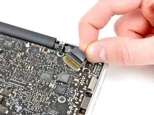
Afferra la linguetta in plastica fissata alla staffa di bloccaggio del cavo dello schermo e tirala verso l'ingresso dell'alimentazione per ruotare la staffa e sbloccarla.
-
Sfila il cavo dello schermo dalla sua presa sulla scheda madre.
-
-
-
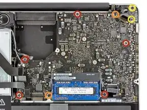
Svita le seguenti nove viti:
-
Cinque viti Torx T6 da 3,6 mm
-
Due viti Torx T6 da 4,3 mm
-
Due viti Torx T6 da 7,2 mm
-
Cinque viti Torx T6 da 3,0 mm
-
Due viti Torx T6 da 3,6 mm
-
Due viti Torx T6 da 6,7 mm
-
-
-
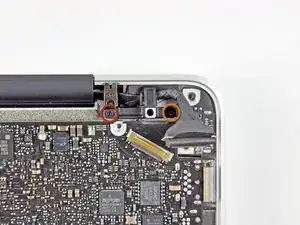
Svita le seguenti viti a croce Phillips:
-
Una vite da 8,6 mm
-
Una vite da 5,5 mm
-
Rimuovi il fermo del cavo dello schermo dalla scocca superiore.
-
-
-
Usa la punta di uno spudger per rimuovere con delicatezza il microfono dall'adesivo che lo fissa alla scocca superiore.
-
-
-
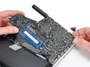
Stando attenti ai diversi connettori vicino ai bordi, solleva la scheda madre dal bordo vicino al lettore CD.
-
Senza piegare la scheda, rimuovila dalla scocca superiore, stando attento al cavo flessibile della scheda di alimentazione che potrebbe impigliarsi nella scocca superiore.
-
Rimuovi la scheda madre.
-


Per rimontare il dispositivo, segui le istruzioni in ordine inverso.

Un commento
If I have a MacBook Pro 13’’ A1278 Mid 2012 with i5 2.5GHz logic board, am I able to put a 2.3 GHz i5 A1278 early 2011 macbook pro logic board onto the Mid 2012 macbook pro?
Sara -
Reminder: When replacing the cable the connector should be placed in from above. This fooled me and I damaged the seat a bit, but not enough to prevent proper connection.
Lee Hughart -
Excellent guide, I feel this bit could be clearer tho. As it is a socket like a fan connector.
Mine had a foam pad on the top like the other lift-up connections and I’ve accidentally taken the socket off.
So just to be aware if your mac has the foam pad on top of this connection.
acupton86 -
I’ve broken the connector of the speaker (on the logic board) by installing it in the wrong way.
Now, I ordered the connector from aliexpress, and have to do some micro soldering and hopefully it’ll work.
Be careful guys
iAziz -
This one took me a moment to figure out. I also have the foam pad and couldn't see where the socket begins. Use the flat end of the spudger and go underneath the red/black cable part close to the socket, then slowly lift it up until it loosens a little, then do the same on the other side.
Chris -
This is a top-down connector. To remove, use a spudger from underneath. To insert, just push on from top gently.
Person37 -