Introduzione

Questa è una guida interna privata utilizzata come prerequisito.

  1. H5WoEX35nCJxJoVc
    H5WoEX35nCJxJoVc
    2h2sAVKwuSa6RdtP
    GOTxbmD6vWqqpGd3
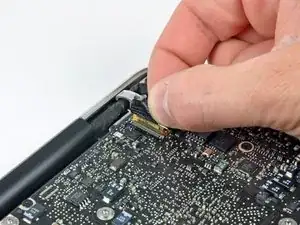
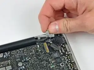
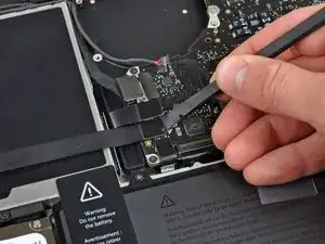
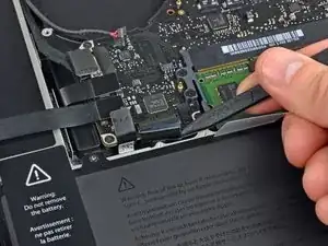
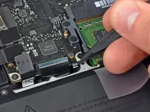
    • Prendi l'aletta in plastica fissata al blocco del cavo dati dello schermo e ruotala verso l'ingresso DC del portatile.

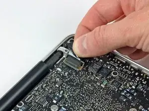
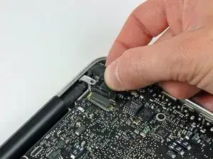
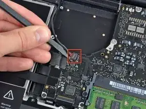
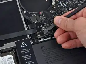
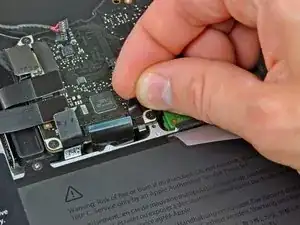
    • Sfila il cavo dati dello schermo dalla sua presa, verso l'ingresso DC del portatile.

  2. gQSfcvhCduWgFmTM
    gQSfcvhCduWgFmTM
    SepnYJ2fJKAXxapY
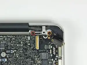
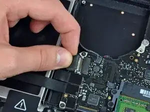
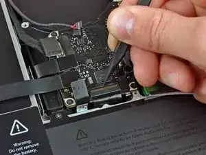
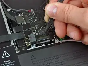
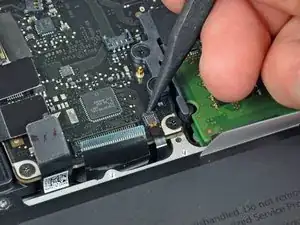
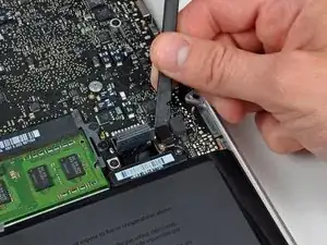
    • Svita le seguenti due viti che fissano la staffa del cavo dati dello schermo al case superiore:

    • Una vite a croce Phillips da 7 mm

    • Una vite a croce Phillips da 5 mm

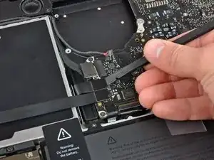
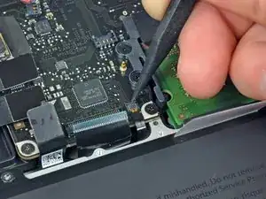
    • Solleva la staffa del cavo dati dello schermo dal case superiore.

    Mine are Torx and got an extra clamp for the cable, just above the left screw

    Martin -

    If you only want to replace the DC-in board, stop here and GOTO 17 (and DO NOT 4 and 6).

    When the Logic board is loose, lift it up on the Harddrive end and shift slightly towards the HD, so that the USB connectors at the outside come free from under the case rim and the board can be lifted up a bit. Then there´s enough room to move the DC in board, pull the cable out with a pair of tweezers, wriggle it out from under the microphone cable and wriggle the new connector in. It can be pushed into the socket with tweezers or a small screwdriver. This worked perfect for me.

    Be careful not to bend the logic board, but otherwise I think there´s much less risk of messing anything up with all the connectors and bits and pieces that need to be loosened and fastened.

    Mike -

  3. 5S2ufCCUjVZjRSVR
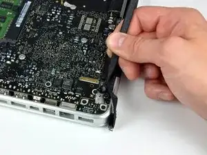
    • Usa la parte piatta di uno spudger per scollegare il connettore del subwoofer e speaker destro dalla scheda madre.

  4. U6VC4QVXgkmSKuKW
    • In questo passaggio scollegherai il cavo della fotocamera. La maggior parte delle macchine hanno un piccolo blocco automatico adesivo incastrato sulla scheda madre per tenere fermo il connettore. Prima di scollegare il cavo, assicurati che questo blocco sia spostato.

    • Tira il cavo della fotocamera verso il lettore CD per scollegarlo dalla scheda madre.

    • Questa presa è in metallo e si piega facilmente. Assicurati di allineare il connettore con la sua presa sulla scheda madre prima di collegare le due parti.

    There is a small piece just below this connector which is just an adhesive block to keep the connector from coming out. It is easiest to peel it up first with a fingernail or spudger then remove the cable. Likewise reinsert the cable before reapplying the adhesive safety stop.

    Justin Jett -

    I couldn't reconnect this cable correctly, so my camera is not working anymore.

    It doesn't matter to me, I didn't used the camera that often...

    But the Ambient Light Sensor uses the camera to control keyboard lighting, so I wasn't able to see my keyboard in the dark anymore... :(

    If you have the same problem, after a couple of google hits I've found this app: https://www.macupdate.com/app/mac/22151/...

    Problem solved! YAY!

    PS: be careful because WIFI passes through this cable as well!!!!

    simbass -

    Look at the photo intently. The connector is inserting not in parallel, but at a slight angle. The bottom corner of the connector is slightly ahead. It is important! Singular metod to insert it.

    Vladimir -

  5. mpLOpCIkoW2xCqif
    mpLOpCIkoW2xCqif
    W2C43m61pZ6Dyqcb
    eo6LQDikRDMpITI5
    • Usa la parte piatta di uno spudger per scollegare i connettori dei cavi del lettore CD, del disco rigido e del trackpad dalla scheda madre.

  6. 4Sf1wHms3aaL4MXg
    4Sf1wHms3aaL4MXg
    AE14gLXhNbiplKt4
    C1TOaQijIPD6LtQn
    • Usa un'unghia o la punta di uno spudger per ruotare verso l'alto l'aletta di bloccaggio sul connettore ZIF del cavo della tastiera.

    • Usa lo spudger per sfilare il cavo della tastiera dalla sua presa.

    When reinserting the keyboard ribbon cable, make sure you push it in all the way (two plastic tools are helpful - one to push it down flat, the other to coax it all the way in). For 3 days after replacing a top case, my MacBook Pro 13" wouldn't start up. I thought the main logic board was fried too. However, reinserting the keyboard ribbon cable again, this time perhaps 1mm farther in, and it started up again! I did the same for the "keyboard backlight ribbon cable" (i.e. reinserted it just to make sure). Really not sure which completed the circuit so is would start, but I suspect the keyboard ribbon cable.

    amiller770 -

    Citazione da amiller770:

    When reinserting the keyboard ribbon cable, make sure you push it in all the way (two plastic tools are helpful - one to push it down flat, the other to coax it all the way in).

    I usually use a piece of sticky transparent office tape and stick it over the flat cable a bit further away from the mating part then pull on it. There is no better way to force the flat cable into a stiff connector without damaging the fragile cable.

    Leo Bodnar -

    As others have stated, if the keyboard ribbon cable isn't fully inserted the MBP will not power on. Leo Bodnar's recommendation to use a piece of transparent office tape did the trick for me. Many thanks Leo!

    Matthew Rankin -

    Inserting the ribbon cable for the keyboard was really difficult, but i was able to get it in using a piece of tape and pulling it up, just like the tape on the keyboard backlight.

    Kelly Legner -

    Using a piece of tape is sheer genius Kelly. My mom once said her definition of genius was an idea that, when you hear it, you say to yourself, “now why didn’t I think of that?” But you never would have thought of it. Brava (or bravo) Kelly!

    JonnyLine -

  7. ORKjULSYLhNuFQUi
    • Rimuovi la piccola striscia di nastro nero dalla presa del cavo a nastro della retroilluminazione della tastiera.

  8. omJ1eHiMfXlFtGVO
    omJ1eHiMfXlFtGVO
    GGYWsYuMi5kZONiq
    TPaIFGAGOPyrUnkA
    • Usa la punta di uno spudger per ruotare verso l'alto l'aletta di bloccaggio sul connettore ZIF del cavo della retroilluminazione della tastiera.

    • Usa lo spudger per sfilare il cavo a nastro della retroilluminazione della tastiera dalla sua presa.

  9. cZ3jLTCybSZqjX1s
    • Usa la parte piatta di uno spudger scollegare il connettore dell'indicatore della batteria sollevandolo dalla sua presa sulla scheda madre.

  10. 1ttqGf15CrXqgESa
    • Usa la punta di uno spudger per rimuovere il microfono dall'adesivo che lo fissa alla scocca superiore.

  11. hlvPHn5hLlwTnykQ
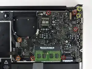
    • Svita le seguenti viti:

    • Cinque viti a croce Phillips da 3,1 mm

    • Due viti a croce Phillips da 3,9 mm

    • Due viti a croce Phillips da 7 mm dalla scheda d'ingresso DC.

  12. uqAscA6i2AwOjsxs
    uqAscA6i2AwOjsxs
    1FKTMO2VElhgwKAM
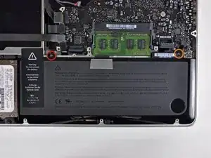
    • Svita le seguenti viti Tri-point che fissano la batteria al case superiore:

    • Una vite Tri-point da 5,5 mm

    • Una vite Tri-point da 13,5 mm

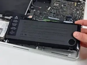
    • Solleva la batteria dal case superiore.

  13. MWPHlxOjnkYSuqrw
    MWPHlxOjnkYSuqrw
    ZgwauAvagMTUNQWZ
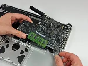
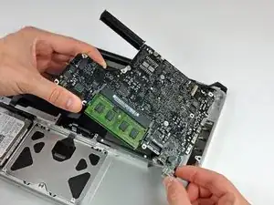
    • Solleva la scheda madre dal suo bordo sinistro e continua finché le porte non escono dal lato del case superiore.

    • Tira la schema madre lontano dal bordo del case superiore e rimuovila, stando attento alla scheda d'ingresso DC che potrebbe impigliarsi.

    • Stai attento a non strappare la presa delicata del connettore del gruppo del microfono.

    When putting the logic board back in place, it's easier to angle the mic down in it's place as you are placing the board in, rather than after the board is seated.

    amiller770 -

Conclusione

Per rimontare il dispositivo, segui le istruzioni in ordine inverso.

Walter Galan

693762 Reputazione

0 commenti