Introduzione
Use this guide when the auxiliary port needs to be replaced.
Ricambi
-
-
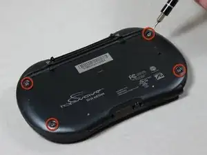
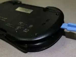
Wedge a spudger in between the front and back panel.
-
Apply leverage downwards to the spudger in order to remove the back panel.
-
-
-
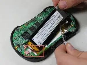
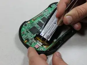
Slide the battery out from under the brown wire-tape.
-
Be careful of the wires still connected to the other end of the battery. Do not pull or damage may occur.
-
-
-
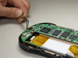
Slowly pull the white plug from its receptor. Grasp its sides firmly with a pair of tweezers and gently wiggle from side to side.
-
-
-
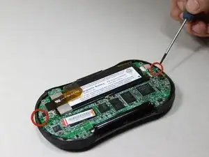
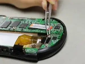
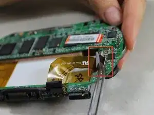
Disconnect 2 brown wire-tape ends from each end of the motherboard. Gently pull straight out with tweezers.
-
-
-
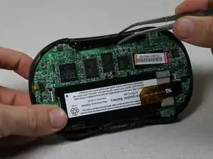
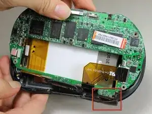
Pull the motherboard and screen component diagonally up and left away from the auxiliary port entrance to remove.
-
-
-
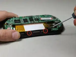
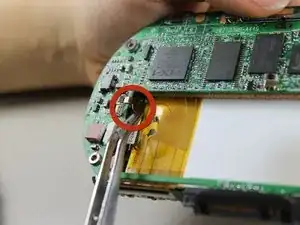
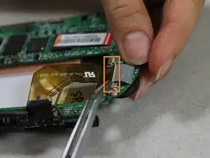
Disconnect the 2 brown wire-tape ends from the left side of the battery slot on the motherboard using tweezers.
-
-
-
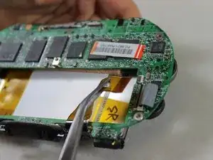
Disconnect the large brown wire-tape from the motherboard.
-
Peel the black tape back from the wire-tape using tweezers.
-
Lift the black, hinged, plastic lock with tweezers to release the wire-tape.
-
The screen and motherboard components can now be separated from each other.
-
-
-
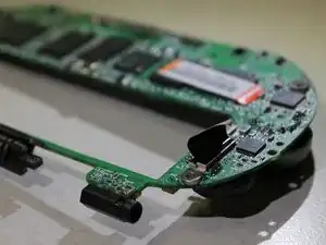
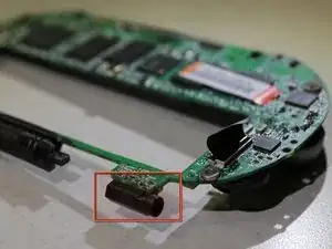
Remove the solder between the auxiliary port and the motherboard carefully with the desoldering pump.
-
To reassemble your device, follow these instructions in reverse order.