Introduzione

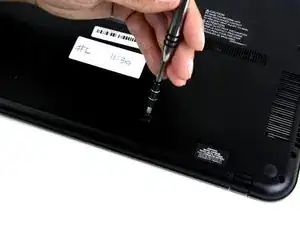
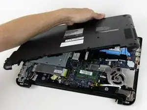
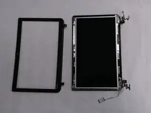
These are the steps for removing the monitor screen from your Toshiba Satellite C55-B5302 laptop. Before starting, make sure you have your Phillips size #0 screwdriver and a systematic way to keep all the unscrewed screws as there are going to be a large number of them with different dimensions. Since we will be working in close proximity with the monitor screen, you should be careful not to scratch it.

  1. N2IQuIrDTPLkEPQP
    N2IQuIrDTPLkEPQP
    krJIhOqkAicJOOi3
    • Flip laptop upside down so you can see the screws.

  2. eKKsUJ51G3gKaNvk
    eKKsUJ51G3gKaNvk
    jtO41mP4roFDu5Vj
    • Using the Phillips #0 screwdriver, remove the two 7 mm screws from the back casing.

  3. AQURyfJFiDZ3Y6rs
    • Pull the battery from the back of the laptop for removal from the laptop.

  4. 1oJeHSFZo16SHHoZ
    1oJeHSFZo16SHHoZ
    UseOQINrFVKWFilW
    Xxaa2OplsfHDFJbJ
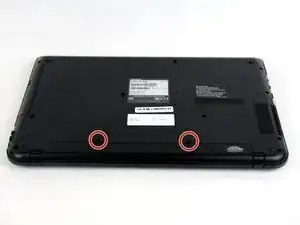
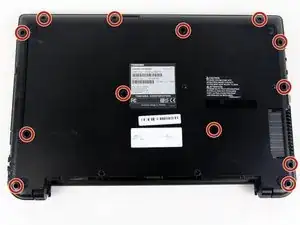
    • Remove the remaining 7 mm screws on the back panel of the laptop with a Phillips #0 screwdriver.

    • Use the plastic opening tool to pry up a corner of the back panel and continue to pop the back panel off.

    • Expect to hear popping as you pull the back panel off.

  5. hIJZhBXZOVIveCZs
    • Disconnect the fan wire from the motherboard.

  6. Db2RTO1vnL6AOXpC
    Db2RTO1vnL6AOXpC
    WZu1gGx2eXDxc4BW
    MELS1QOmurPAIyeR
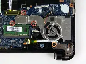
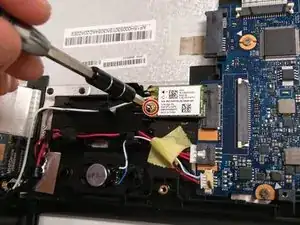
    • Remove the three 3 mm screws with a Phillips #00 screwdriver.

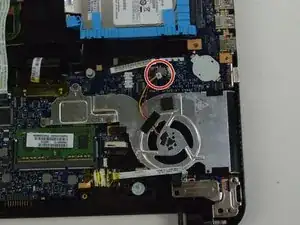
    • Remove the 5 mm screw with a Phillips #0 screwdriver.

  7. lbnnCLdTHJPfvbBF
    • You can now lift the fan out of the laptop.

  8. BAkZrMTojScpvbVY
    BAkZrMTojScpvbVY
    2fOifoJx2RlVynjh
    F5RBWgwBmohxAwts
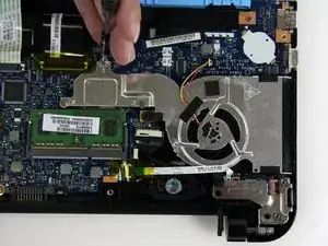
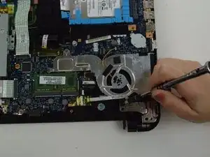
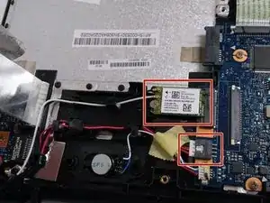
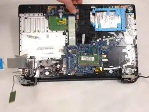
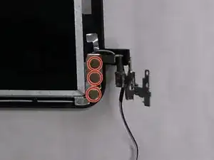
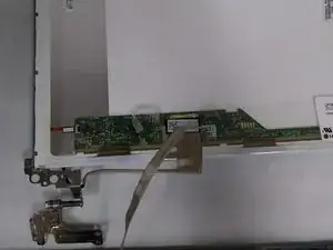
    • After the fan has been removed, lift the hinge so as to get access to the parts below it.

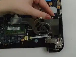
    • Remove the the black colored cable that is now exposed.

  9. S2stZJ2hd1uZGNrK
    S2stZJ2hd1uZGNrK
    YuKtNHo1wLFAjm1N
    3ag2YMumqjJlPayj
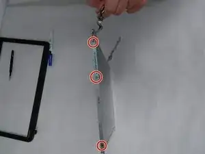
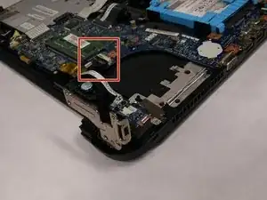
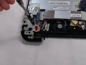
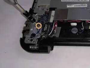
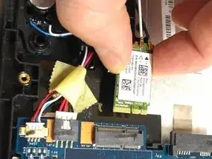
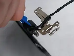
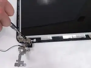
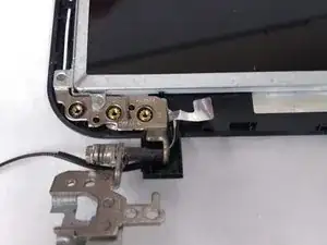
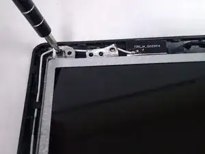
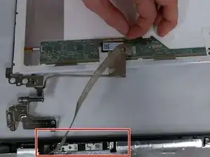
    • Remove the 7 mm Phillips #0 screw on the other hinge.

    • Remove the 3.1 mm Phillips #0 screw on the the same hinge.

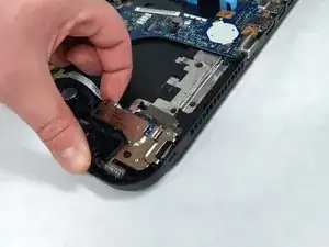
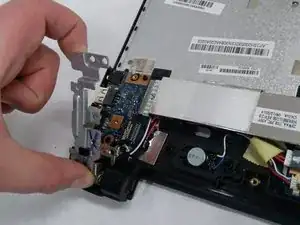
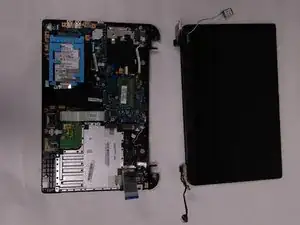
    • Lift the hinge up and towards you.

  10. M6NcXSLawXIeuM4X
    M6NcXSLawXIeuM4X
    tVbI6YXJKkyYj66C
    • Pull out the wide cable to reveal the components underneath.

  11. VraqRKEXdwWCdael
    VraqRKEXdwWCdael
    KKiokpD1Uj1GESYn
    • Remove the 3.1 mm Phillips #0 screw holding the chip in place.

    • Pull out the chip.

  12. gekNRq3oNqu14okC
    gekNRq3oNqu14okC
    bIfiekxsfrtVbgGT
    Js5tJrSvpXBMiyfB
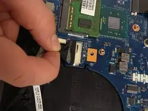
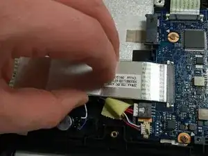
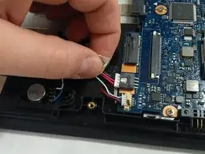
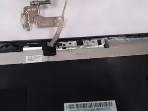
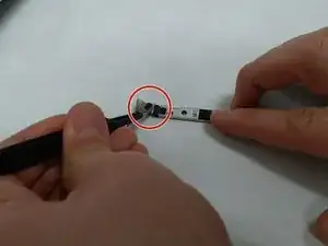
    • Hold the cable that is to be removed.

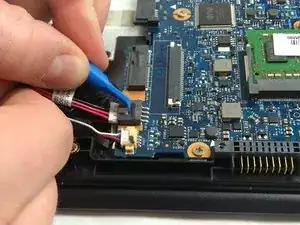
    • Use an iFixit opening tool to push down on the white protrusion of cable connector.

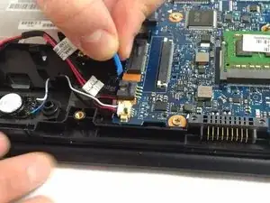
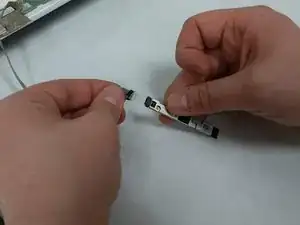
    • Now you can pull out the cable.

  13. GTARY5hRpNNsm1HW
    GTARY5hRpNNsm1HW
    PaAA6HeZBKtDDIVt
    YTM5MGsV2fwk6r1i
    • Pivot and lift up the monitor and separate it from the base of the laptop.

  14. 6f6PQuR3HEEm3eW2
    6f6PQuR3HEEm3eW2
    RYtAhMdLncQPndvI
    RdjndM1BihHgXdML
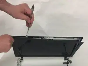
    • Use an iFixit opening tool to separate the two halves of the bezel starting at both the plastic hinges.

    • Use the metal spudger to separate the rest of the bezel.

    • Be careful not to scratch the screen with the metal spudger.

    • You may hear some sounds as the clips on the bezel disconnect from the back cover. This is normal.

  15. MWXKvlcuiasMFSnC
    MWXKvlcuiasMFSnC
    ZXqS5ap4Y1xprbnM
    Pu4sH4OoirUIGuQk
    • Remove the three 4.1 mm Phillips #0 screws attaching each hinge to the screen.

  16. ZWd2ulGXd5bTWMSV
    ZWd2ulGXd5bTWMSV
    ogdCe6QFlSFGmhKo
    • Remove the two 3.1 mm Phillips #0 screws at the top of the screen.

  17. evwmnAtAukvbUVbJ
    evwmnAtAukvbUVbJ
    JVjVVAwlLRTqe6dT
    PgSvEBNPF1CysQwa
    • Pull up on and turn over the screen to expose the wire connecting the webcam to the screen.

    • Be careful not to pull up on the screen too far and damage the wire.

  18. InARTTY2TnZxMKNk
    InARTTY2TnZxMKNk
    sJDSZ5NVDCE2HBGi
    TnxFKxvGFDX1aOBN
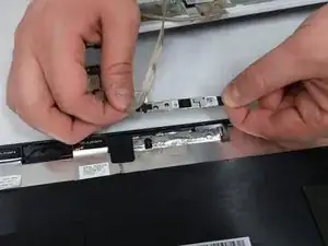
    • Once the screen has been detached and turned over, remove the webcam from its place on the bezel.

    where does that short cord on the monitor go?

    superarmstrong860@gmail.com -

  19. eaUJeR4pCVwokZsl
    eaUJeR4pCVwokZsl
    frvxxEn4jLCxJr2P
    • Carefully, take off the tape connecting the webcam to the circuit board using a set of tweezers.

    • Once the tape has been removed, you can disconnect the webcam from the wire completely.

  20. jdNdj1RfN2CQ6mc2
    jdNdj1RfN2CQ6mc2
    pBrKBQKErWcguujR
    R3HUxpobcTUIGHJ4
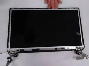
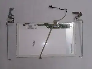
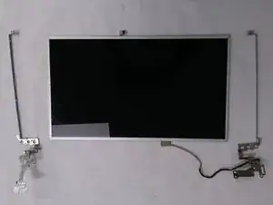
    • Have the screen along with the metal hinges stand upright on one side.

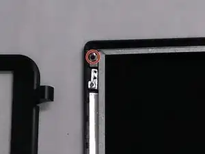
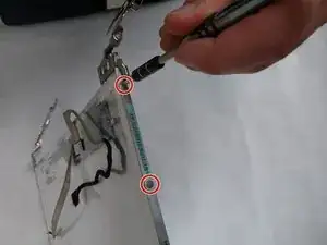
    • Remove the three 3 mm Phillips #0 screws from the metal frame attached to the hinge.

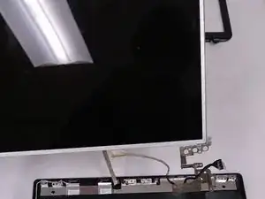
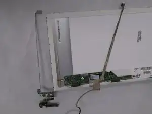
    • Separate the metal frame from the rest of the screen.

  21. q35SSdNJWKeCnvEZ
    q35SSdNJWKeCnvEZ
    OmgbLe6FDqvTnvVb
    • Repeat the previous steps to separate the metal frame on the other side.

Conclusione

To reassemble your device, follow these instructions in reverse order.

Ebin Daniel

Membro da: 25/03/19

109 Reputazione

0 commenti