Introduzione
A relatively common failure on Ubiquiti switches is a power supply failure. A switch with a power supply failure will fail to turn on if powered on mains power, but will turn on if given 24-25V on the separate 25V port.
This guide shows how to replace the power supply inside the switch with a generic power supply.
Strumenti
Ricambi
-
-
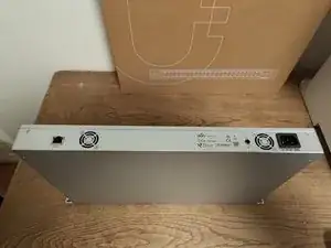
Identify the four screws (two at the back, two at the bottom) holding the switch closed. One is hidden behind a sticker.
-
You do not need to remove the rack brackets
-
Use a PZ2 screwdriver to remove the screws
-
Slide the lid a short distance towards the front to open the switch.
-
-
-
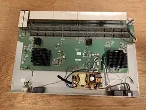
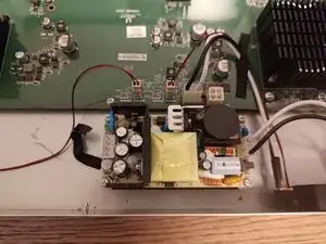
Identify the power supply. It is the yellow separate board at the bottom.
-
There may be burn marks on the power supply from the failure.
-
Remove it from the switch (4 screws, PZ2)
-
Save the power supply and screws. You will need them later.
-
-
-
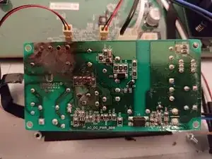
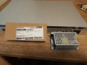
Unbox the replacement Powersupply
-
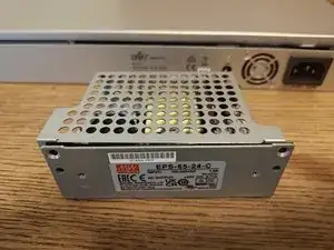
Unscrew the two screws at the front, and the two at the back to remove the top metal screen
-
Finally removed the two back screws to free the board from the bottom metal screen
-
-
-
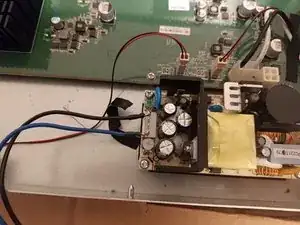
Insert the replacement Powersupply in the switch, and secure it with the original 4 screws
-
Dimensions of the replacement power supply should be identical to the original one.
-
The main power connector should fit on the new power supply.
-
-
-
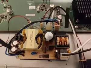
Unsolder the 24v leads from the old power supply.
-
Identify the positive and negative output on the new power supply. On this one, positive is at the bottom of the picture.
-
Solder in the 24v leads on the new power supply
-
Solder in the blue (+) lead on the bottom of the output connector
-
Solder in the black (-) lead on the top of the output connector
-
Alternatively, get a proper connector that fits on the power supply.
-
Finally, connect the 24V on the main board
-
To reassemble your device, close the lid and secure the four screws.