Introduzione

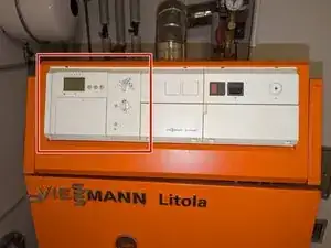
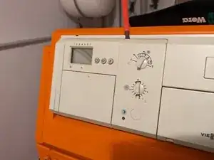
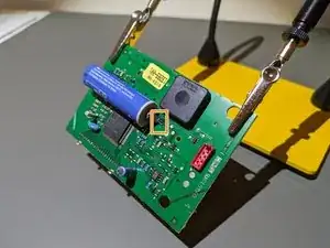
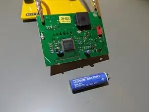
The Duomatik Control Unit/HMI is equipped with a built-in industrial-grade 3.6V 2400mAh AA (Mignon) Lithium (LiSOCl2) Battery, used for maintaining clock functionality and preserving timer settings during boiler shutdowns or power outages. Although these robust cells typically offer prolonged lifespan, eventual failure is inevitable.

Should your boiler frequently lose time and settings, it might signal the need for a battery replacement.

This in guide we will walk you through the process of replacing the battery.

Note

If you're replacing the battery as a preventive measure, when you power on the module after the repair, it might initially seem broken to you. The module will enter an error mode due to time loss, locking all functions except for setting the time. Therefore, your first step would be setting the clock before accessing other features.

  1. 2OT3a6yBkVRiGdXs
    2OT3a6yBkVRiGdXs
    vUAmHRRAvgn41siF
    • Locate the shutoff switch of your boiler and press it.

    • The switch is usually positioned right next to the flame-resistant door leading to the boiler room and labeled as Boiler Emergency Shutoff.

  2. CAlHHMNQJLJWLh5T
    • Locate the HMI module of the Duomatik, that you want to remove.

  3. qcyhAF2YhSm3etZB
    qcyhAF2YhSm3etZB
    TNnWqH3ZKhxZ2bDG
    • Insert a flathead screwdriver or a Spudger into the small notch on top of the module to gently loosen it.

  4. vWvQrSVK2JWbasPV
    vWvQrSVK2JWbasPV
    vLFSp2slCXsB6lgf
    • Pull out the module straight toward yourself.

  5. DQLJvAZF4lUoZeSg
    DQLJvAZF4lUoZeSg
    NwQfySmVm36PJQSB
    fEdqfWs6SvIIEh2w
    • Place the module on its front.

    • The back of the module is held in by four clips. Use Spudgers to hold the clips open while you remove the back.

    • You might meet a bit of resistance from the little red connector holding the two PCBs inside together.

  6. PJwpi2jciu3mTlYf
    PJwpi2jciu3mTlYf
    Eh6WYyQNrERJDGWk
    XYtLXdnjMZauQOFg
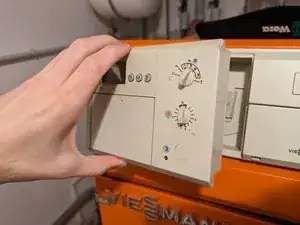
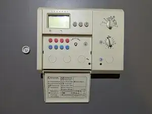
    • Place the module on its back.

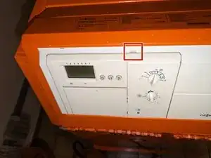
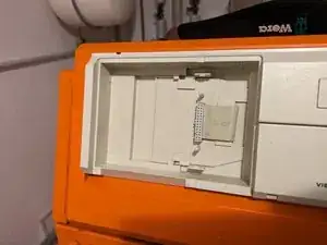
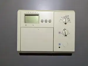
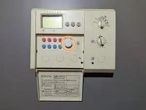
    • Open the flap that covers the buttons for setting the timer.

    • Remove the encoder knob by pulling it off.

  7. 16KYeFCKMQhj3RmZ
    16KYeFCKMQhj3RmZ
    vmbdNudGXqsAYjbf
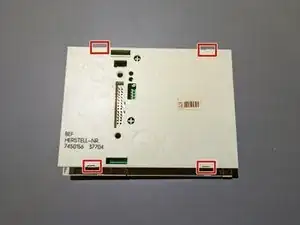
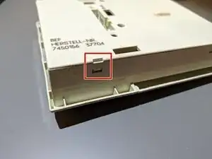
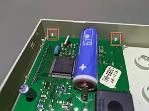
    • Release the first two clips holding the PCB inside the housing.

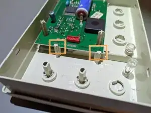
    • Release the last two clips holding the PCB inside the housing.

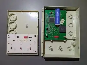
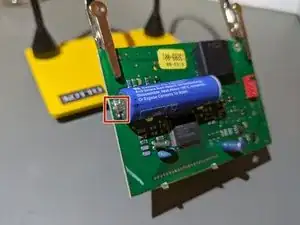
    • Remove the PCB from the housing.

    • The last two clips might be a bit hard to release, though take care to not use too much force and break them.

  8. AJImWifXRDYosPEk
    AJImWifXRDYosPEk
    HuspeT3SXNHkVWQ2
    DhlJlHHvmflkoETR
    • Desolder the negative connection.

    • Desolder the positive connection.

    • See this guide on how to solder and desolder connections.

Conclusione

To reassemble your device, follow these instructions in reverse order.

Take your e-waste to an R2 or e-Stewards certified recycler.

Sebastian

Membro da: 19/08/18

19300 Reputazione

0 commenti