Introduzione
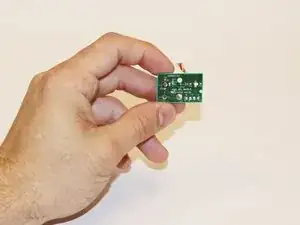
Infrared blasters emulate an IR signal. This is used to remote-control other equipment in the vicinity of the Kinect. The IR blasters are mounted on the heat sink inside the Kinect.
-
-
Remove the sticker on the underside of the device.
-
Remove the four 3.1x23.5 mm T10 screws underneath the sticker.
-
While you're at it, remove the four 3.1x7.5 mm T10 screws beneath the sticker. Make note of the sizes and locations of the screws.
-
-
-
Remove the back panel.
-
Remove the black panels on either side of the Kinect, and remove the 3.1x7.5mm T10 screws underneath them.
-
-
-
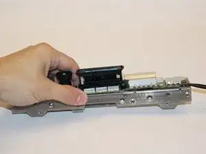
Using your thumbs, press firmly against the outer case on either side of the stand. This will disengage the internal assembly.
-
Lift the internal assembly with the spudger.
-
Remove the assembly from the case. You now have access to the inner shell of the kinect, along with the heat sink, microphone, and LED sensor.
-
-
-
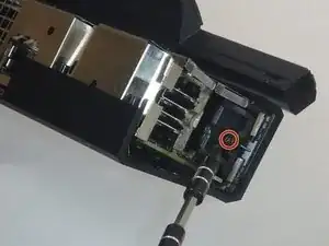
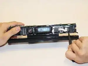
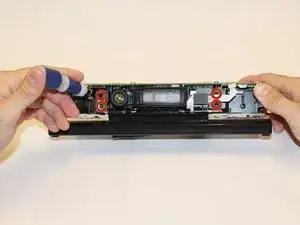
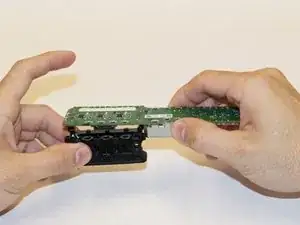
Remove the eight 2.9x7.6 mm T9 screws from the rear of the internal case.
-
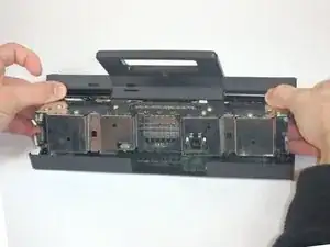
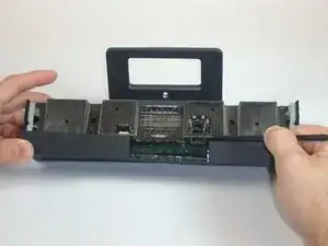
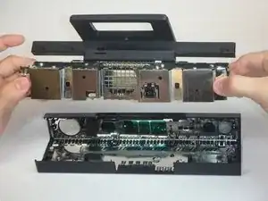
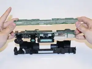
Lift the internal metal case from the plastic shell enclosing the heat sink assembly.
-
-
-
Disconnect the ribbon cable between the sensor driver board and the motherboard.
-
Remove the 3.0x7.5 mm T9 screw holding the sensor driver board to the heat sink.
-
Remove the infrared sensor board for the Kinect.
-
-
-
Detach the ribbon cable leading to the microphone with the tweezers.
-
Remove the four 3.1x7.7 mm T9 screws connecting the microphone to the heat sink assembly.
-
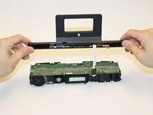
Remove the stand.
-
-
-
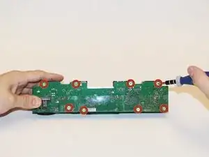
Remove the eight 3.0x7.6 mm T9 screws from the motherboard.
-
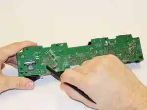
Peel away the plastic film from the motherboard using the spudger.
-
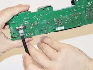
Detach the ribbon cable leading to the color camera using the spudger.
-
-
-
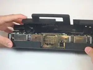
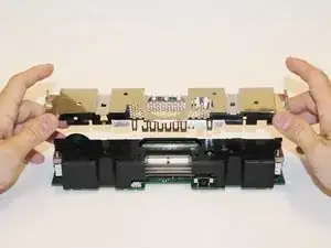
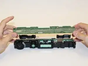
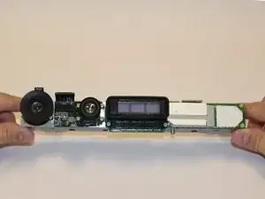
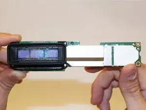
Lift the motherboard and the heat sink assembly from the plastic shell. The components attached to the heat sink are now accessible.
-
-
-
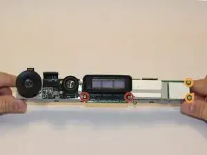
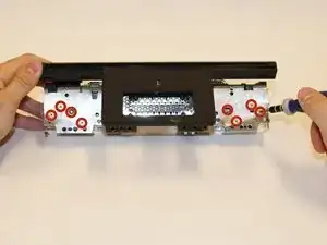
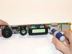
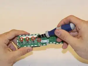
Using a T5 torx driver, remove the four 1.9x10 mm screws on the corners of the blasters.
-
Remove the two 1.9x5.1 mm T5 screws on the right-hand side of the board.
-
-
-
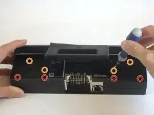
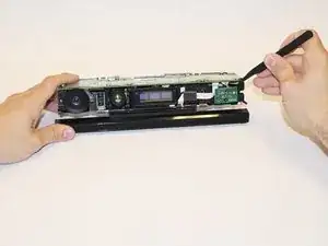
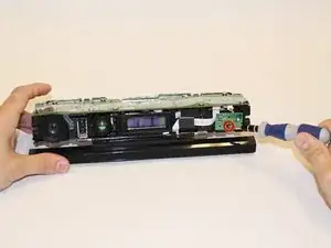
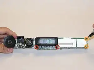
Remove the four 1.9x5.1 mm T5 screws from the back of the board.
-
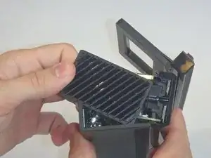
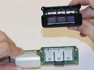
Gently remove the IR blasters from the board.
-
Obtain replacement blasters.
-
To reassemble your device, follow these instructions in reverse order.
Un commento
please where to buy those IR blasters ???