Introduzione
Do you need to remove the cover of your bObsweep to replace something inside? The guide will help you remove the cover, which serves as the housing for the bObsweep. If you need to replace anything underneath, such as the bumper or a touch sensor, you must first remove the cover.
For this guide, you will need a flat head screwdriver (found in bObsweep’s kit) and a Phillips head screwdriver. You do not need to perform any difficult steps but be careful putting your fingers near the cracks and edges when handling the cover and its components.
-
-
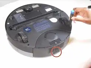
Depress the tab on the side of the dustbin to disengage its latch. It is spring loaded and will partially pop out. Remove it from its housing.
-
-
-
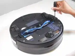
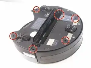
Flip the bObsweep over and remove the main brush’s screw (13.7mm Flat) with a flathead screwdriver.
-
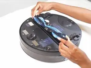
Lift and remove the main brush and its plastic bearing end cap.
-
-
-
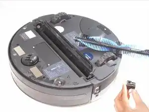
Remove the two screws (9.9mm Phillips #1) next to the rotating front wheel.
-
Remove the two screws (9.9mm Phillips #1) below the wheels on either side of the dustbin compartment.
-
Remove the screw (9.9mm Phillips #1) to the side of the brush motor.
-
Remove the screw (9.9mm Phillips #1) inside the brush compartment.
-
-
-
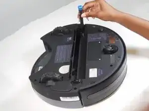
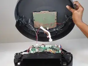
Carefully hold the top and bottom halves together and flip the bObsweep upright.
-
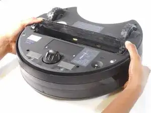
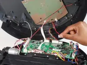
Lift the cover to reveal the mainboard.
-
-
-
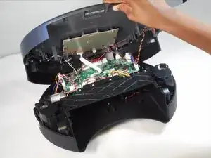
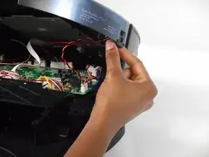
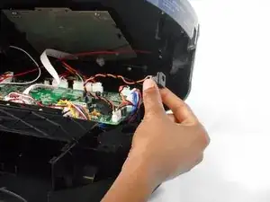
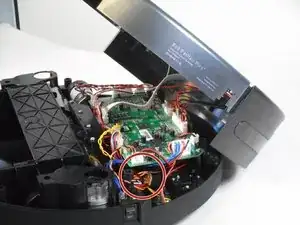
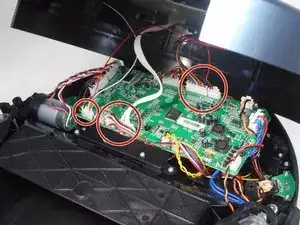
Depress the tabs on the circuit plugs and lift them directly upward to remove:
-
The multicolored nine-wire circuit plug at the top edge of the board.
-
The red and black wire circuit plug directly next to it.
-
The seven white wire circuit plug on the bottom edge of the board.
-
The red, white, and black wire circuit plug on the bottom left corner of the board.
-
Follows steps 6-9 for reassembly.