Introduzione
Use this guide to replace a damaged clutch cover.
-
-
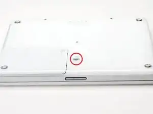
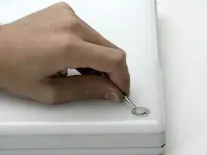
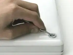
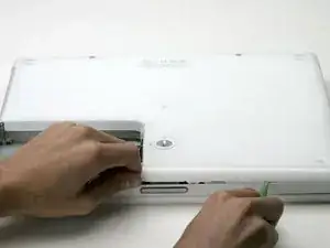
Use a coin to rotate the battery locking screw 90 degrees clockwise.
-
Lift the battery out of the computer.
-
-
-
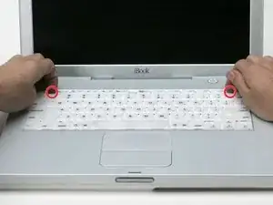
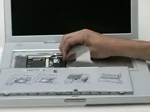
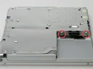
Pull the keyboard release tabs (highlighted in red) toward you and lift up on the keyboard until it pops free.
-
If the keyboard does not come free, use a small flathead screwdriver to turn the keyboard locking screw 180 degrees in either direction and try again.
-
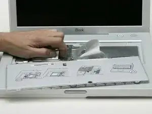
Flip the keyboard over, away from the screen, and rest it face-down on the trackpad area.
-
-
-
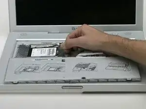
Pull the keyboard cable up from the logic board, holding the cable as close to the connector as possible.
-
-
-
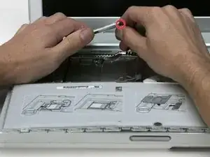
Use a spudger or small flathead screwdriver to pry up the three metal rings that housed the rubber bumpers.
-
-
-
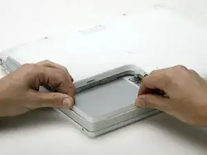
Push the thin rims of the lower case surrounding the battery compartment in, bending them past the tabs, and then lift up to free that corner of the lower case.
-
-
-
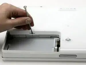
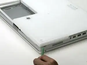
Use a small flathead screwdriver to pry out the slot's lower rim and pull up on the lower case to free the slot from the tabs holding it.
-
-
-
Run a spudger along the seam between the lower case and upper case on the front of the computer to free the tabs locking the lower case.
-
Pull up on the lower case and continue to use the spudger as necessary until you hear three distinct clicks.
-
-
-
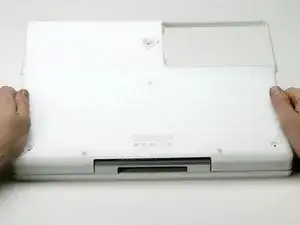
Once the front and sides of the lower case are free, turn the computer so that the back is facing you.
-
Pull the lower case up and toward you until the back tabs pop free.
-
-
-
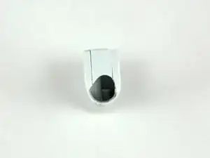
Remove the small greasy springs with white plastic caps from either side of the battery contacts.
-
-
-
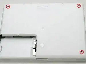
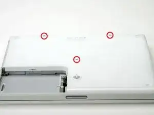
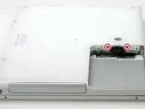
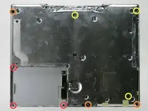
Remove the following 9 screws on the bottom of the computer:
-
Three 3 mm Phillips around the battery compartment.
-
Three 5 mm Phillips on the left and bottom edges.
-
Three 14.5 mm Phillips on the top and right edges (you may have to peel back the foil tape to reveal the screw near the security lock slot).
-
-
-
Turn over the computer and open it.
-
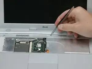
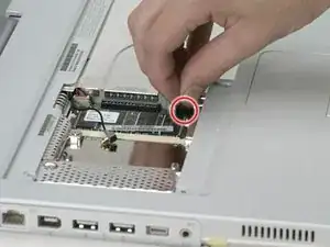
Pry up the magnet covering a Phillips screw near the middle of the computer.
-
-
-
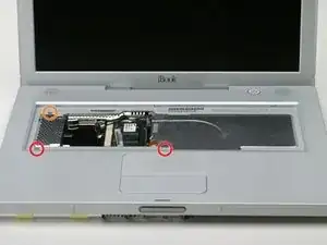
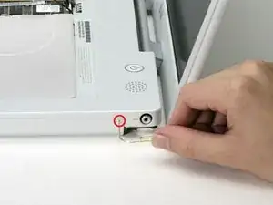
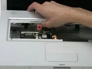
Remove the following 3 screws on the edges of the keyboard area:
-
Two 6 mm Phillips underneath the keyboard area.
-
One 9 mm Phillips above the keyboard area.
-
-
-
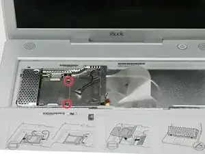
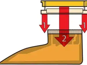
With your fingernails, grasp the locking bar on either side and pull up a small amount (about 1/16" or 2 mm).
-
After disengaging the locking bar, slide the cable out of the connector.
-
-
-
Loosen the trackpad connector by pulling the top piece up slightly, freeing the trackpad ribbon.
-
Slide the orange trackpad ribbon out of the connector.
-
-
-
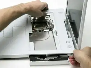
Use a straightened paperclip to open the optical drive tray, and pull it out about halfway.
-
-
-
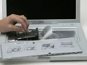
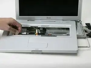
Lift the upper case from the left side and use your other hand to pull out the right side in order to clear the power receptacle.
-
-
-
Lift the upper case enough to disconnect the blue and white power cable from the logic board.
-
Using your fingernails or a dental pick, carefully pry the connector from its socket.
-
-
-
Lift the upper case off completely and disconnect the red and black speaker cable from the logic board.
-
-
-
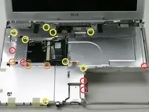
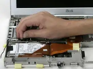
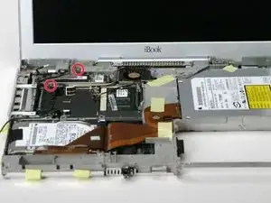
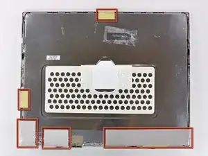
Remove the following 16 screws:
-
Five 3 mm Phillips (these have smaller heads than the others).
-
Three 5 mm Phillips.
-
Eight 6 mm Phillips.
-
-
-
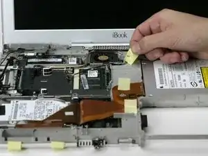
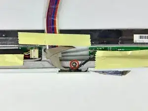
Peel back three strips of yellow tape in the bottom, left corner.
-
Peel back one strip of foil tape near the audio-out port, one near where the trackpad connects to the logic board, and one near where the screen latch used to be.
-
-
-
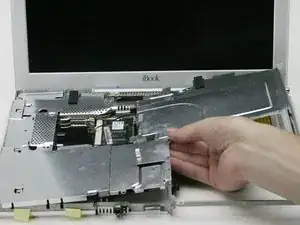
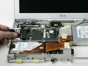
Lift the top shield up from the right side, minding the upper left corner, which may catch on the metal framework.
-
-
-
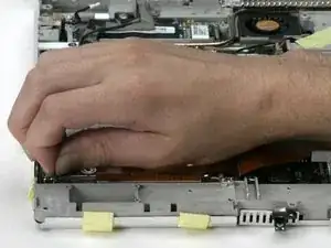
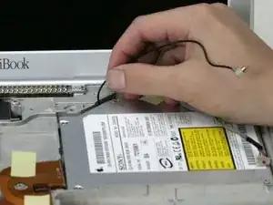
Disconnect the microphone cable from the front, left corner of the logic board.
-
Peel back the black tape and free the microphone cable from the hard drive.
-
-
-
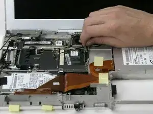
Disconnect the inverter cable from the logic board.
-
Carefully deroute the inverter cable from beneath the optical drive.
-
-
-
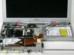
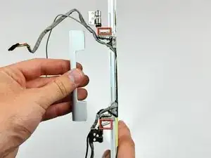
Remove the single Phillips screw on the outer edge of either hinge (two screws total).
-
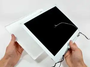
Tilt the display back to get over two small nubbins, and then slide it directly from the case and away.
-
-
-
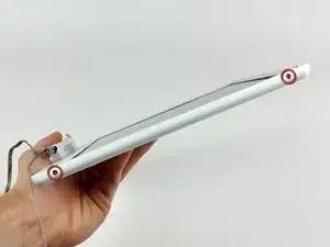
Use a 1.5 mm hex screwdriver to remove the two hex screws on either side of the display (four screws total).
-
-
-
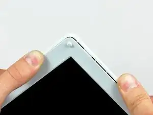
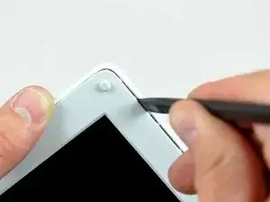
Insert the flat end of a spudger into the gap between the front and rear bezels.
-
Rotate your spudger until it is parallel to the front face of the display.
-
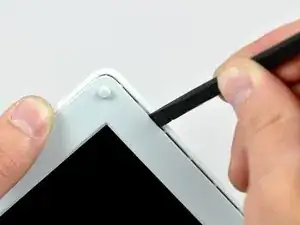
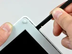
Run the spudger around the perimeter of the display to separate the rear bezel from its retaining clips.
-
-
-
Remove the pieces of readily removable tape from around the perimeter of the display.
-
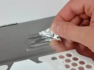
Carefully remove the aluminum tape covering the display data cable connection.
-
-
-
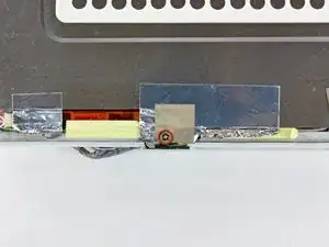
Remove the single screw inserted through the piece of EMI tape near the bottom edge of the display.
-
Use the tip of a spudger to remove the small washer under the screw you just removed.
-
-
-
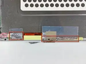
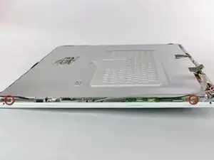
Remove the two Phillips screws securing each side of the LCD to the clutch hinge frame (four screws total).
-
-
-
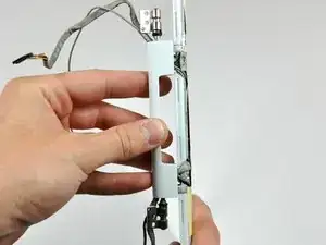
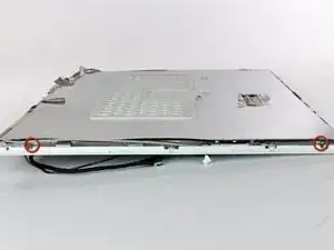
Remove the second of the two Phillips screws securing the clutch cover to the cast aluminum frame of the clutch hinges.
-

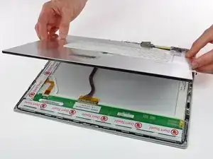

To reassemble your device, follow these instructions in reverse order.
