Introduzione
Partially disconnecting the Logic Board to get to antenna connections. Internal Prerequisite.
Strumenti
-
-
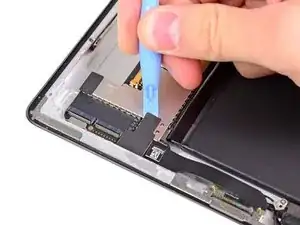
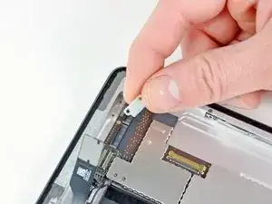
If present, remove the piece of tape covering the end of the dock connector cable.
-
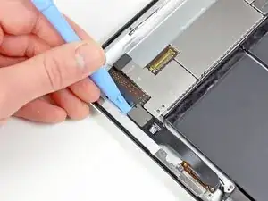
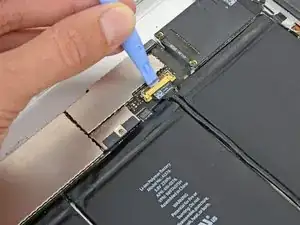
Use the edge of a plastic opening tool to carefully pry the dock connector cable's connector up from its socket on the logic board.
-
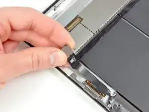
Peel the dock connector ribbon cable off the rear panel.
-
-
-
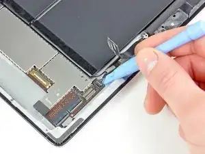
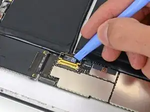
Place the prying tool beneath the 4 wires on the end of the connector and gently pry the speaker cable connector straight up from its socket on the logic board. Do not pry from the opposite end of the connector as this will break the 4 solder points on the underside of the socket and will require a microsolder repair.
-
-
-
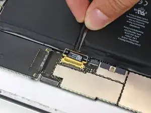
Use a plastic opening tool to flip up the retainer securing the upper component board cable connector to its socket on the logic board.
-
Pull the connector away from its socket on the logic board.
-
-
-
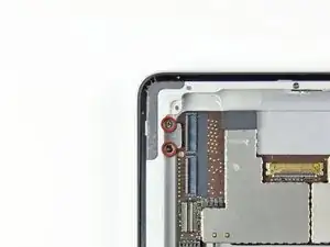
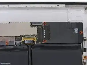
Remove the two 2.1 mm Phillips screws securing the logic board bracket to the rear case near the digitizer cable socket.
-
Remove the logic board bracket from the rear case.
-
-
-
Remove the four 2.6 mm Phillips screws securing the logic and communications boards to the rear panel.
-
-
-
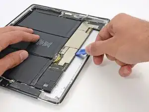
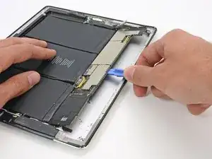
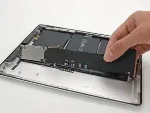
Use a plastic opening tool to gently pry the logic board up from the rear case.
-
The logic board is adhered to the rear case; work slowly and uniformly to peel up the glue without damaging the board.
-
To reassemble your device, follow these instructions in reverse order.