Introduzione
-
-
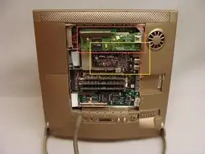
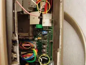
Unplug the logic board connections to the PRAM battery and fan.
-
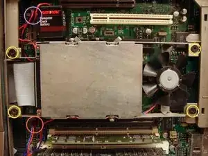
Remove the PRAM battery from it's Velcro mounting.
-
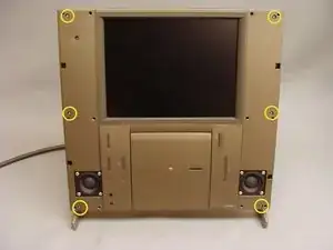
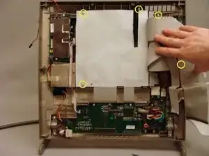
Remove the four #0 Philips screws securing the hard drive and processor fan assembly.
-
Remove the hard drive and processor fan assembly.
-
-
-
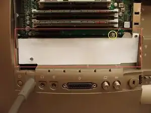
Remove the white plastic shield
-
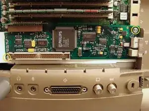
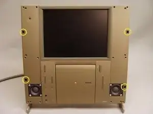
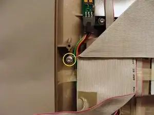
Remove the T6 torx screw securing the logic board to the frame.
-
-
-
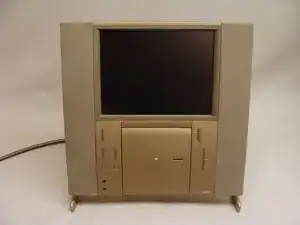
Turn the TAM around with the front facing you.
-
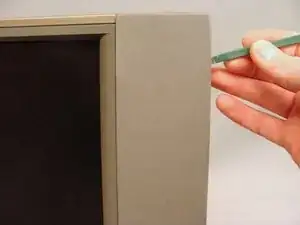
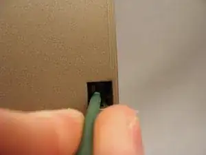
Use a spudger to gently loosen the speaker covers from their press-fit snaps. Remove the speaker covers.
-
-
-
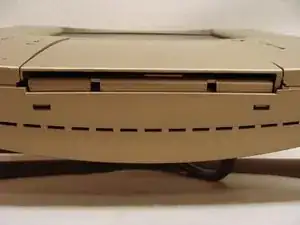
Gently pull the tabs toward the center to release the latches hold the front and back together. These tabs are fragile but release easily. Use caution.
-
Lean the top forward and lift up to pull the front case from it's bottom latches.
-
DO NOT TRY TO REMOVE THE FRONT CASE. It is still connected to the back case by several wires and cables.
-
-
-
Disconnect the pink and white backlight inverter cable and the black and white right speaker cable from behind the floppy disk drive on the right side.
-
On the left side, disconnect the 50-pin SCSI ribbon cable, analog audio cable and power cable from the CD-ROM drive.
-
Disconnect the black and white left speaker cable.
-
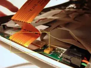
Disconnect the flat, orange display data cable.
-
Open the top case to the left like a book. There will be one more 50-pin cable to disconnect from the front control panel board.
-
-
-
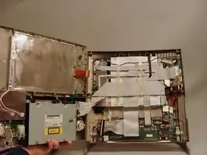
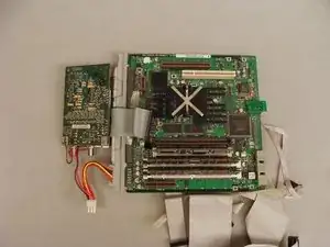
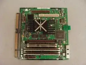
The easiest method to remove the logic board is to remove it with the tuner card and cabling.
-
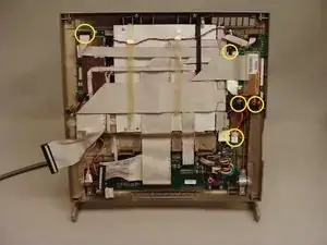
Disconnect the five cables illustrated.
-
-
-
Carefully peel back the tape securing the cables to the white, plastic logic board cover. Pull the cables back to reveal the back side of the logic board.
-
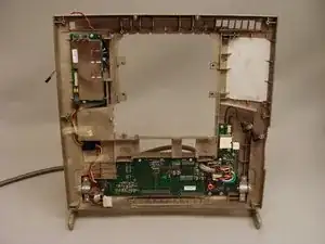
Remove the five T10 screws holding the logic and tuner boards to the back case.
-
-
-
Lift the logic board from the left edge then straight up to remove it from the rear case.
-
The logic board slides out of the cabling connector.
-
To reassemble your device, follow these instructions in reverse order.
4 commenti
Hi,
One of the member of my Forum is looking for the Bose subwoofer including the power cable. Have you an idee on where could he find it ?
Thx.
Raziel
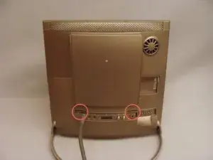
It's missing the step to remove the two torx screws on the upper back side, below the cover with all the holes, after Step 5
Deagol -
Dose anybody know what goes in the top-most chip slot that is empty? Is that for an L2 Cache chip?
garo211 -