Introduzione
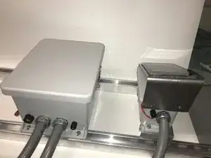
In this teardown, you will be shown how to take apart (and reassemble) an Open-Storm valve node pair.
-
-
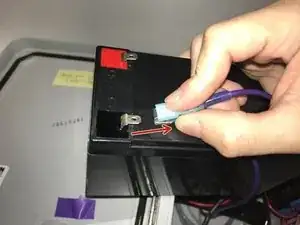
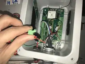
For the large node unclip the battery
-
For the smaller node, detach the battery from the solar charger
-
-
-
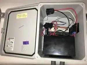
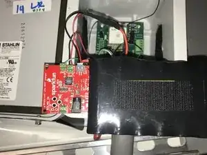
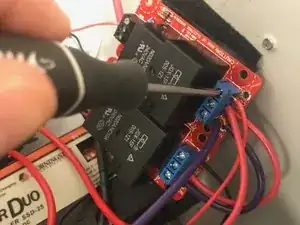
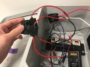
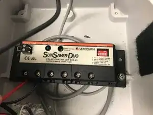
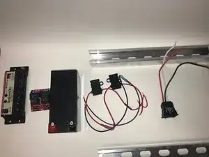
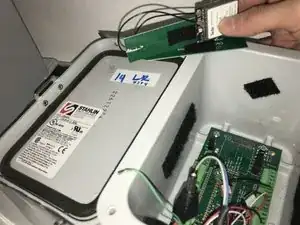
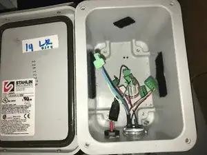
SunSaver Duo
-
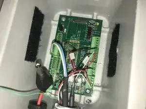
Relays
-
Battery
-
Battery Wires/Connectors
-
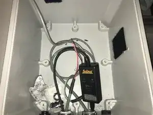
Switch (still connected to the small enclosure via the conduit)
-
-
-
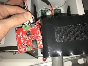
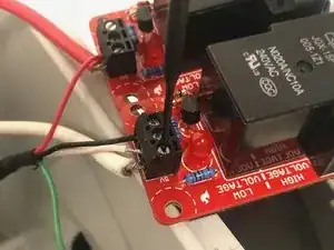
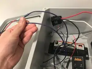
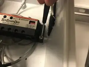
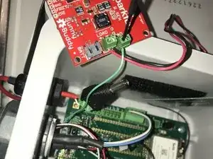
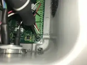
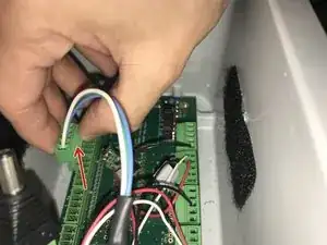
Pull out the solar charger terminal from the board
-
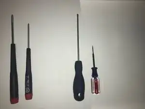
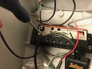
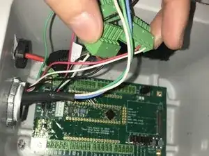
Unscrew the green wire from the solar charger using the (small) flat head screwdriver
-
-
-
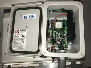
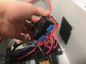
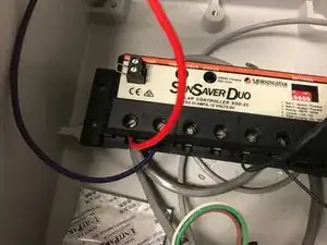
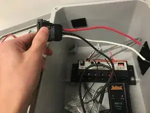
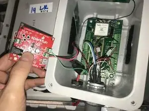
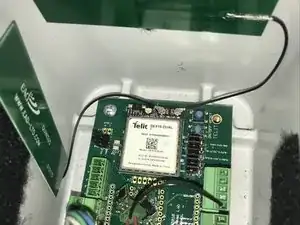
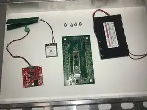
Solar charger with an attached terminal
-
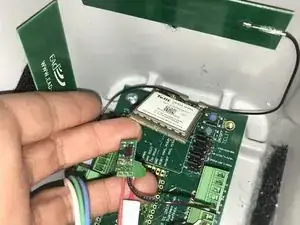
Cell module with attached antenna on the "ANT" and "GPS" pins
-
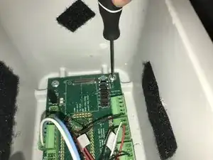
Board with the four screws
-
The battery
-