Introduction

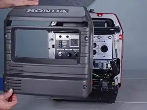
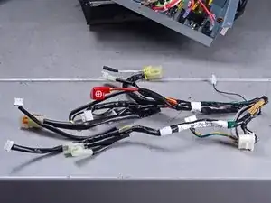
This guide shows how to remove and replace the control wire harness for the Honda EU3000IS1AWK 3000 watt generator.

This wire harness connects the control panel to the various generator assemblies.

You will need a long shaft (at least 5 inches) Phillips screwdriver in order to complete this guide.

You will also need some small zip ties to replace the ones that are removed during the procedure.

  1. UbGMSPUHmu5Emipg
    UbGMSPUHmu5Emipg
    EOqTsUAtCi2KFHFw
    • Before you begin, make sure the generator is off and cool to the touch.

    • Use a large flathead screwdriver to unlock the maintenance cover.

    • Open the maintenance cover.

  2. sJT2NiSJDvqIrsat
    sJT2NiSJDvqIrsat
    CGOaGS1UbALvMXom
    • Use a Phillips screwdriver to remove the screw securing the spark plug cover.

    • Remove the spark plug cover.

  3. PQCWqaPkWnK4k6CD
    PQCWqaPkWnK4k6CD
    EoOtaOPaXQtnwgWu
    • Grab the plastic housing at the end of the spark plug wire.

    • Pull firmly to disconnect the wire from the spark plug.

  4. 23thAcA2vMUnJWdU
    23thAcA2vMUnJWdU
    C5yxoojJaXjxcEnE
    • Turn the fuel valve to the cutoff position.

  5. iDvNAmrIrrmIpxK6
    iDvNAmrIrrmIpxK6
    P6XwTuMvPDD4ye2E
    F4Ipy2BmDPGU5Ebk
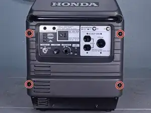
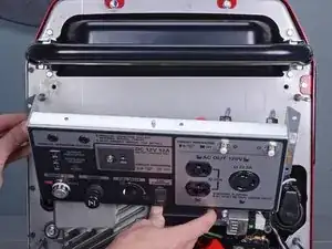
    • Use a 10 mm socket to remove the four capped nuts securing the front cover.

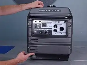
    • Remove the front cover.

  6. B4mZdaK3yv6sOwTA
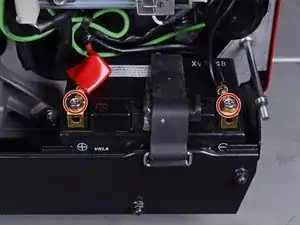
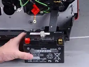
    • Use an 8 mm socket to disconnect the battery wires from the battery terminals.

    • Disconnect the black negative cable first to prevent the risk of shorting the battery.

    • During reassembly, connect the black negative cable first. Make sure you reconnect the wires in the correct polarity.

  7. Rtd2gVSNJQMZfDER
    Rtd2gVSNJQMZfDER
    2VUsPrTZH6UGGAHL
    • Unclip the battery strap from the lower plate.

  8. JUpfTWDkcOFirXJP
    • Remove the battery.

  9. RDZUVKlwTMFoDWqW
    RDZUVKlwTMFoDWqW
    r4IFmRkNHWogk3sr
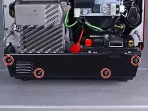
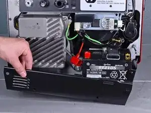
    • Use a 10 mm socket to remove the four capped nuts securing the lower plate.

    • Set these capped nuts apart. They look similar, but are smaller than the front cover nuts.

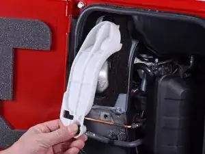
    • Remove the lower plate.

  10. bsIFORL3CwVedQRS
    bsIFORL3CwVedQRS
    SkSZvRQJ3uLuFixC
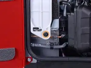
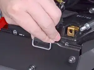
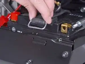
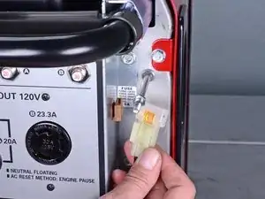
    • Insert a flathead screwdriver into the top of the brown fuse clip in order to release the fuse holder.

    • Detach the fuse holder from the brown clip.

  11. QuHfgHuEQ4VthYnL
    QuHfgHuEQ4VthYnL
    QXdqRVvHKZyuPUNu
    • Use pliers to lift and disconnect the choke cable from the choke stay.

    • During reassembly, be sure to test the choke to ensure that it is properly connected.

  12. Kr1wUlNnspfySpYL
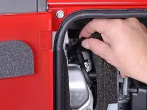
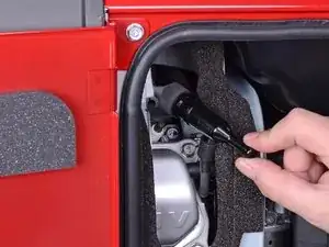
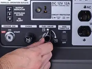
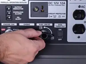
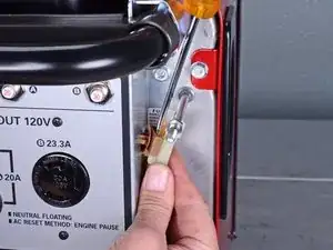
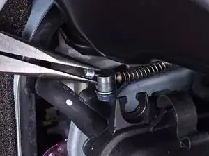
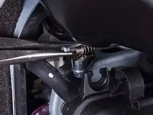
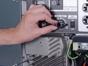
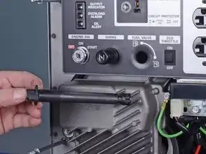
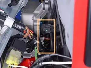
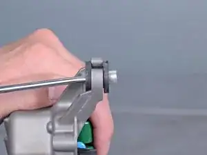
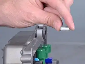
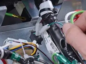
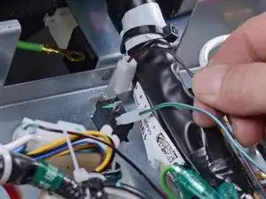
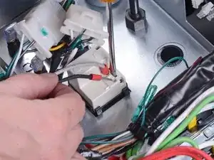
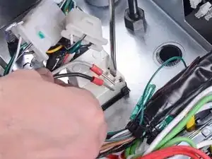
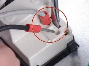
    • Use a long shaft Phillips screwdriver to remove the deeply recessed screw securing the fuel cutoff switch.

    • Be careful not to turn the fuel cutoff switch while you remove the screw.

  13. WxlUVQ2yhw2BNXyB
    WxlUVQ2yhw2BNXyB
    1dkhrTXLElKMKoaR
    • Remove the fuel cutoff switch.

    • During reassembly, be sure to test the switch to ensure that it is properly installed.

  14. RLiROE5UcjRcT6LM
    • Use a 10 mm socket to remove the four bolts securing the control panel.

  15. 2BWAAS6wDiR1qRHQ
    2BWAAS6wDiR1qRHQ
    ToGduqcQLsj2TYUY
    • Carefully tilt the control panel downwards.

    • The control panel will still be connected to many wires and cables. Be careful not to strain any of the connected wires.

  16. yisIoCCa4EQOvp4f
    yisIoCCa4EQOvp4f
    5AWchIdoWZJSdff5
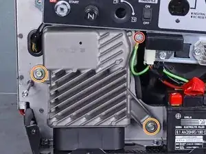
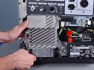
    • Remove the following bolts securing the inverter:

    • One 8 mm ground bolt

    • Three 10 mm bolts (one behind the control panel)

  17. XhIjcjWBGTa1DoD2
    XhIjcjWBGTa1DoD2
    DRNHXClo6UvsENDZ
    ZqiNgEEOEqirHYd2
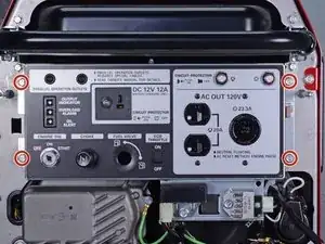
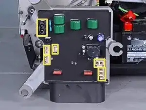
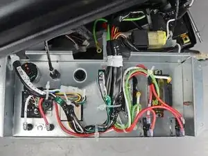
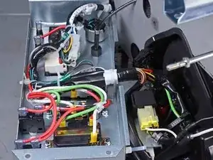
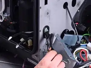
    • Reach behind the inverter along the edges and disconnect the six connectors from the back of the inverter.

    • All the connectors use locking tabs, so you will have to squeeze them in order to release them.

    • The third image shows the locations of all six sockets on the inverter.

    • Reassembly tip: Every socket on the inverter is different, so you can't plug something into the wrong place. Do not force the connectors into their sockets.

  18. KXJh6hti66cTXpwL
    KXJh6hti66cTXpwL
    kxbSKsNJr5IAcah5
    • Remove the inverter.

  19. 5hFMIbRljs3bKVaC
    5hFMIbRljs3bKVaC
    WfYTfi4RVX2vEJLM
    • If you are replacing the inverter and the replacement did not come with rubber mounts, follow the next two steps to transfer them over.

    • Use a screwdriver to push the metal collar out of the center of the rubber mount.

  20. RUUJZ23DwxTcyEyh
    RUUJZ23DwxTcyEyh
    OLMHZcWsYnYJbDgp
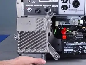
    • Squeeze the mount and remove it from the inverter.

    • Repeat the procedure with the remaining mounts and transfer them to the replacement inverter.

  21. XJcGeOYOd3pXSjQH
    XJcGeOYOd3pXSjQH
    GEvLcckh1gSvlBTn
    • The remaining steps show all the connectors you need to disconnect in order to replace the wire harness.

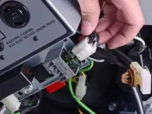
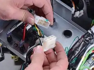
    • To help keep track of the connectors, disconnect each one from the old harness and immediately connect it to the new harness.

    • Most connectors are keyed to plug in one orientation. Do not force the connectors.

    • Be sure to replace any cable ties you removed along the way.

    • During reassembly, use these images as reference for how the harness is secured to the control panel.

  22. esNd2ebuHNXBVeFf
    esNd2ebuHNXBVeFf
    XHYcgjOmd1fNCqVK
    • Unplug the five-wire starter relay connector.

  23. fVkDdaXZ34XYVPSM
    fVkDdaXZ34XYVPSM
    QktfLLkZAPemmpiy
    • Unplug the starter motor's black and white barrel connectors.

    • The wires should be connected to their respective colors.

  24. E1kku2T3fG4TT3Ox
    • Unplug the two-wire oil switch connector.

  25. 5RSPxhLhGLVjCdPj
    • Unplug the four-wire rectifier connector from the bottom right corner of the control panel.

  26. U3yR2MKfxN35cj4J
    • Unplug the four-wire regulator connector from the bottom edge of the control panel.

  27. AHoRjxXFibYGqdfa
    • Unplug the green ground barrel connector.

  28. DKbxV4MHGaIM4ZoA
    DKbxV4MHGaIM4ZoA
    RlLVZjmBoV3DFRei
    QcZMpqZJXfgyQJf4
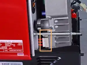
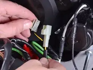
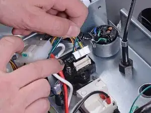
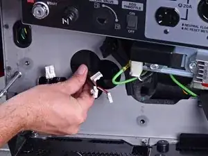
    • Unplug the green and brown wires connected to the eco-throttle switch.

    • Be sure to connect these wires to their respective sockets.

  29. 5FUZQ4pTeIUQlDHG
    • Unplug the six-pin combination switch connector.

  30. SVMCXOLHQA2VsRoq
    SVMCXOLHQA2VsRoq
    tfxyiQZRLbJpJpK2
    feja2NeLXBplRQjr
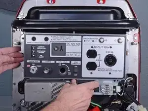
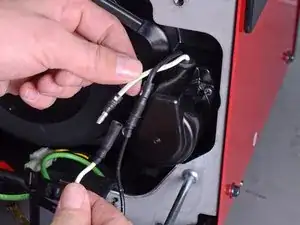
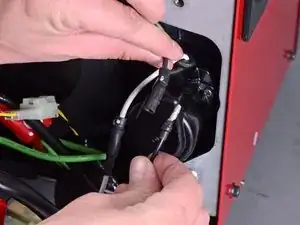
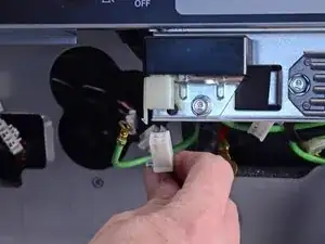
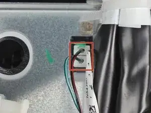
    • Insert a flathead screwdriver into the slot behind the DC receptacle in order to release the receptacle wires.

    • Pull and unplug the black and grey wires from the DC receptacle.

    • Be sure to connect these wires to the proper sockets.

  31. 6DnrZD2O3pTNkGPT
    • Unplug the six-wire ignition control module connector.

  32. bWMR3HcHORVQFLnx
    bWMR3HcHORVQFLnx
    aLYcMOhyfCencZ3X
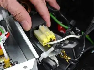
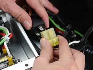
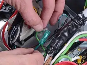
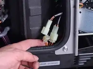
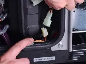
    • Unplug the two winding connectors next to the air filter box.

    • Do not plug in the new wire harness yet.

  33. TDPoIWeGXmm4VTbK
    TDPoIWeGXmm4VTbK
    sFsedFSVsj6DAcAP
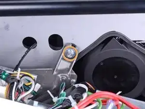
    • Pull the existing wire harness out of the front frame.

    • Thread the replacement harness through the same cutout.

    • Route the three inverter connectors on the replacement harness through the double circular cutout in the front frame.

  34. Q5x6dBJykurNwQNr
    • Connect the two winding connectors to the new harness.

  35. ZpkVArKBbFOBCBiV
    • The old wire harness should be completely removed.

    • Compare your harness routing with the images in step 21. Be sure that the harness is securely fastened to the generator.

Conclusion

To reassemble your device, follow these instructions in reverse order.

Arthur Shi

Member since: 03/01/18

225807 Reputation

0 comments