Introduction
Every fixer should know their way around a multimeter, which has just north of a zillion uses for testing electronic components and circuits. Follow along to master the three most basic functions of a multimeter.
Tools
-
-
A continuity test tells us whether two things are electrically connected: if something is continuous, an electric current can flow freely from one end to the other.
-
If there's no continuity, it means there is a break somewhere in the circuit. This could indicate anything from a blown fuse or bad solder joint to an incorrectly wired circuit.
-
-
-
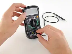
Plug the black probe into the COM port on your multimeter.
-
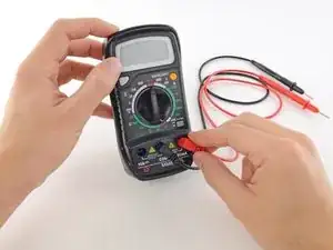
Plug the red probe into the VΩmA port.
-
-
-
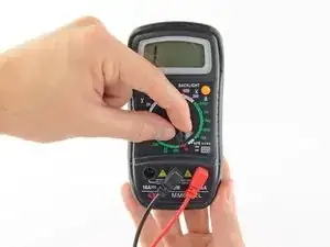
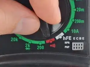
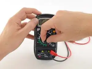
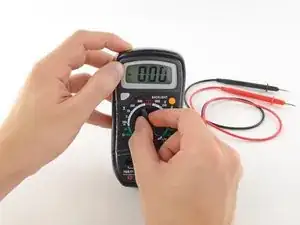
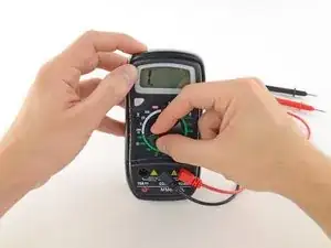
Switch on your multimeter, and set the dial to continuity mode (indicated by an icon that looks like a sound wave).
-
-
-
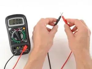
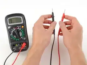
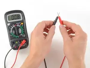
The multimeter tests continuity by sending a little current through one probe, and checking whether the other probe receives it.
-
If the probes are connected—either by a continuous circuit, or by touching each other directly—the test current flows through. The screen displays a value of zero (or near zero), and the multimeter beeps. Continuity!
-
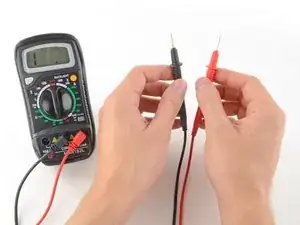
If the test current isn't detected, it means there's no continuity. The screen will display 1 or OL (open loop).
-
-
-
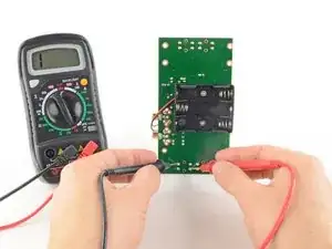
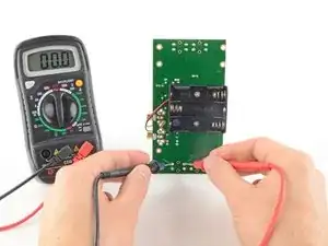
To complete your continuity test, place one probe at each end of the circuit or component you want to test.
-
As before, if your circuit is continuous, the screen displays a value of zero (or near zero), and the multimeter beeps.
-
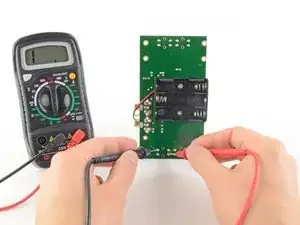
If the screen displays 1 or OL (open loop), there's no continuity—that is, there's no path for electric current to flow from one probe to the other.
-
-
-
If your multimeter doesn't have a dedicated continuity test mode, you can still perform a continuity test.
-
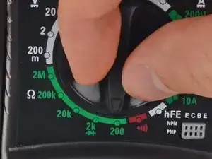
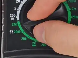
Turn the dial to the lowest setting in the resistance mode.
-
-
-
In this mode, the multimeter sends a little current through one probe, and measures what (if anything) is received by the other probe.
-
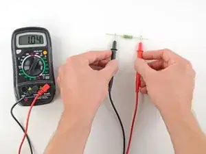
If the probes are connected—either by a continuous circuit, or by touching each other directly—the test current flows through. The screen displays a value of zero (or near zero—in this case, 0.8). Very low resistance is another way of saying that we have continuity.
-
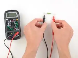
If no current is detected, it means there's no continuity. The screen will display 1 or OL (open loop).
-
-
-
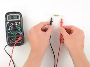
To complete your continuity test, place one probe at each end of the circuit or component you want to test.
-
As before, if your circuit is continuous, the screen displays a value of zero (or near zero).
-
If the screen displays 1 or OL (open loop), there's no continuity—that is, there's no path for electric current to flow from one probe to the other.
-
-
-
Plug the black probe into the COM port on your multimeter.
-
Plug the red probe into the VΩmA port.
-
-
-
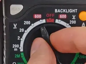
Switch on your multimeter, and set the dial to DC voltage mode (indicated by a V with a straight line, or the symbol ⎓).
-
Most multimeters are not autoranging, meaning you will need to set the correct range for the voltage you expect to measure.
-
Each setting on the dial lists the maximum voltage it can measure. So for example, if you expect to measure more than 2 volts but less than 20, use the 20 volt setting.
-
If you're not sure, start with the highest setting.
-
-
-
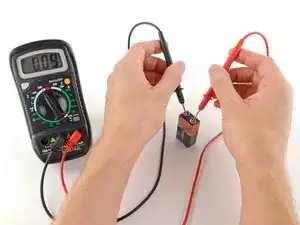
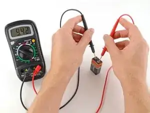
Place the red probe on the positive terminal, and the black probe on the negative terminal.
-
If your range was set too high, you may not get a very accurate reading. Here the multimeter reads 9 volts. That's fine, but we can turn the dial to a lower range to get a better reading.
-
If you set the range too low, the multimeter simply reads 1 or OL, indicating that it is overloaded or out of range. This won't hurt the multimeter, but we need to set the dial to a higher range.
-
-
-
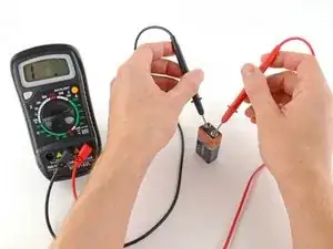
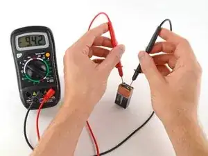
With the range set correctly, we get a reading of 9.42 volts.
-
Reversing the probes won't do any harm; it just gives us a negative reading.
-
-
-
To begin, make sure no current is running through the circuit or component you want to test. Switch it off, unplug it from the wall, and remove any batteries.
-
Plug the black probe into the COM port on your multimeter.
-
Plug the red probe into the VΩmA port.
-
-
-
Switch on your multimeter, and set the dial to resistance mode.
-
Most multimeters are not autoranging, meaning you will need to set the correct range for the resistance you expect to measure. If you're not sure, start with the highest setting.
-
-
-
Place one probe at each end of the circuit or component you want to test.
-
If your multimeter reads close to zero, the range is set too high for a good measurement. Turn the dial to a lower setting.
-
If you set the range too low, the multimeter simply reads 1 or OL, indicating that it is overloaded or out of range. This won't hurt the multimeter, but we need to set the dial to a higher range.
-
The other possibility is that the circuit or component you are testing doesn't have continuity—that is, it has infinite resistance. A non continuous circuit will always read 1 or OL on a resistance test.
-