Introduction
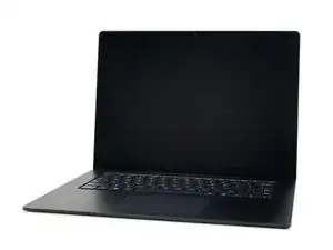
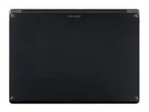
This guide demonstrates how to replace the LCD panel in your Microsoft Surface Laptop 3 (15").
-
-
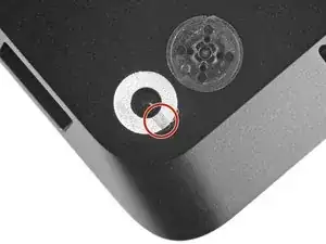
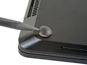
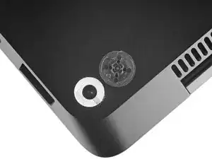
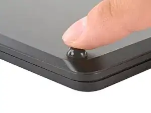
Each foot has a hidden indent that will simplify removal.
-
To make sure the spudger is in the indent, insert it at the nearest long edge, pushing parallel to the short edges of the laptop, as shown.
-
-
-
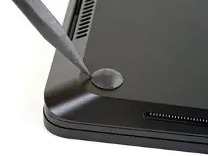
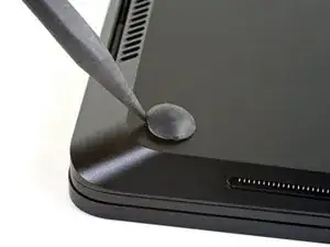
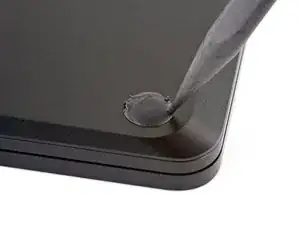
Insert the pointed end of a spudger underneath one of the two rear feet, at its rear edge.
-
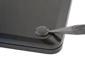
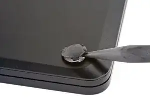
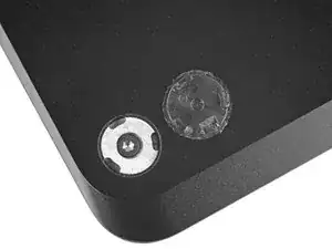
Push the spudger underneath the foot and pry up to release it.
-
Repeat to remove the second rear foot.
-
-
-
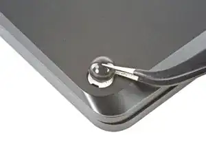
Insert the pointed end of a spudger underneath one of the two front feet, at its front edge.
-
Push the spudger underneath the foot and pry up to release it.
-
Repeat to remove the second front foot.
-
-
-
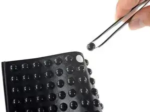
Note that the front and rear feet are different.
-
Note that the front feet are directional and only clip in one way.
-
-
-
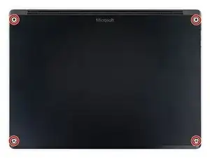
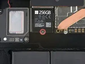
Use a T5 Torx driver to remove the four 3 mm screws in the foot cavities securing the upper case to the device.
-
-
-
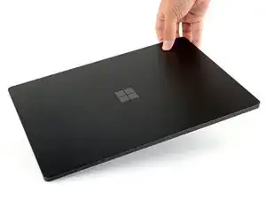
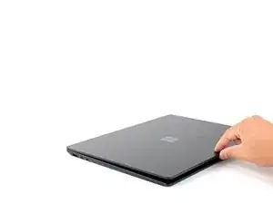
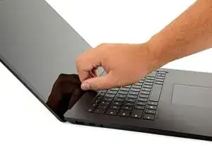
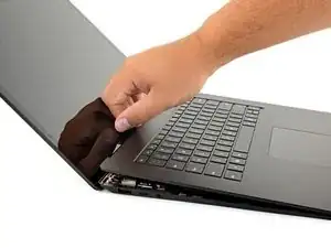
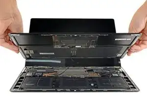
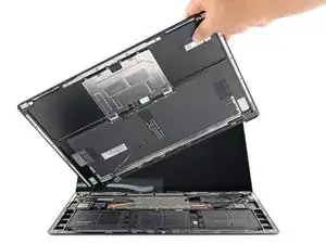
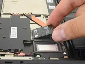
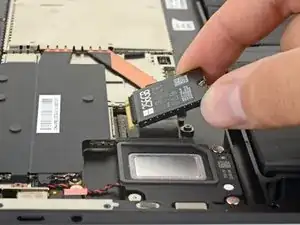
Grip the top edge of upper case above the keyboard and lift straight up to release it.
-
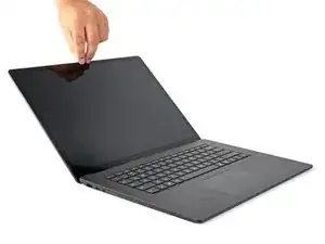
Lift the front edge of the upper case up and away from the laptop, taking care to not strain the keyboard and touchpad ribbon cable underneath.
-
-
-
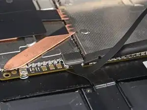
Insert the flat end of a spudger underneath one edge of the ribbon cable connector, and pry up to release it.
-
Remove the ribbon cable from the motherboard.
-
-
-
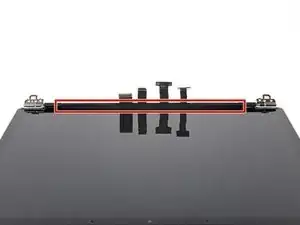
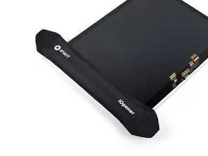
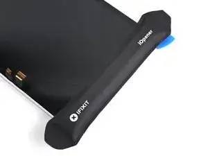
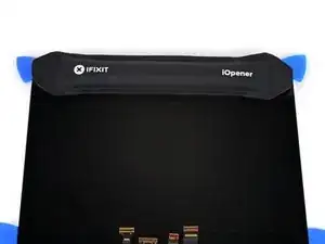
Apply a heated iOpener to the long plastic cable bracket at the base of your screen for one minute to soften its adhesive.
-
-
-
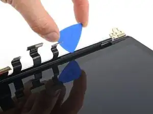
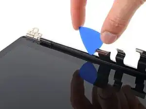
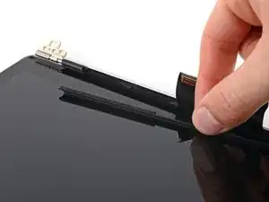
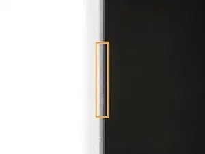
Insert an opening pick into the seam between the cable bracket and the LCD back cover, to the right of the cables.
-
Slide your pick toward the left hinge to separate the adhesive.
-
-
-
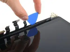
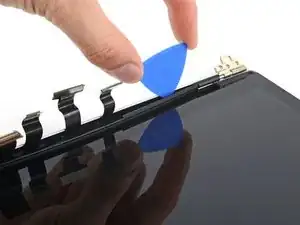
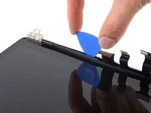
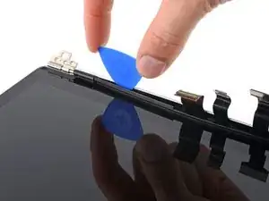
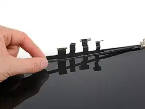
Insert your opening pick again to the left of the cables and slide it toward the hinge to fully separate the adhesive.
-
-
-
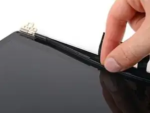
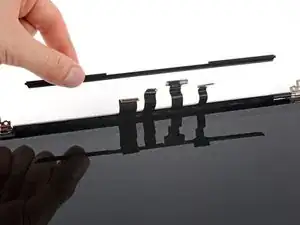
Grab the middle of the cable bracket and pull it away from the cables.
-
Pull the left side of the bracket out of its recess near the hinge.
-
-
-
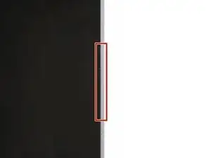
The screen used in this guide has a smaller gap on the right side, which would be harder to start with.
-
The left edge has a wider gap, which would be easier to start with.
-
-
-
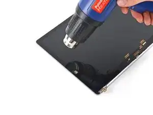
Note the location of the adhesive we're softening on this step: long strips secure each short edge of the screen.
-
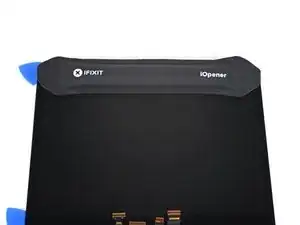
Apply a heated iOpener to the left edge of the screen for three minutes.
-
-
-
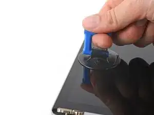
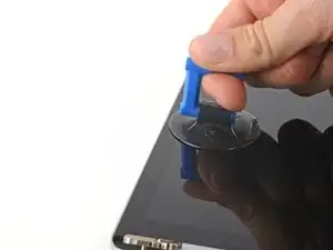
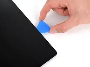
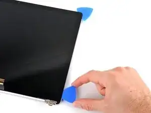
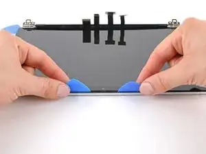
Place a suction handle on the left edge of the screen, as close to the edge as possible.
-
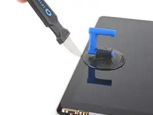
Pull up on the suction handle with a strong and steady force to slightly lift the glass.
-
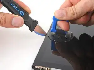
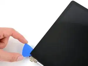
Insert a Jimmy, iFlex, or other thin metal tool at a 45-degree angle in the gap between the screen and back cover.
-
-
-
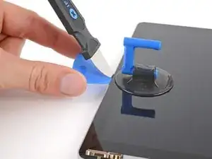
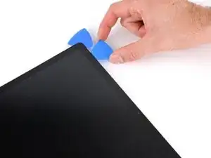
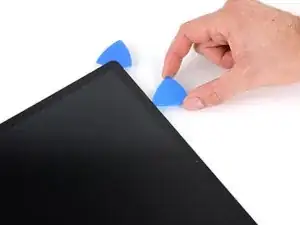
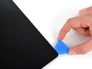
Slide your opening pick toward the hinge.
-
Leave your pick in the bottom left corner of the screen to prevent the adhesive from resealing.
-
-
-
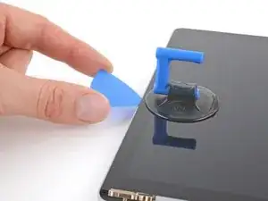
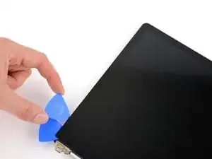
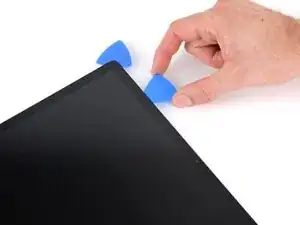
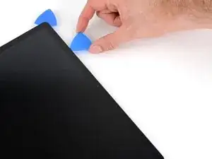
Insert a second opening pick next to the one in the bottom left corner.
-
Slide the pick to the top left corner to completely separate the left edge adhesive.
-
Leave this pick in the top left corner to prevent the adhesive from resealing.
-
-
-
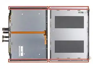
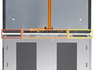
The left section of adhesive extends 69 mm (2.7 in) from the left edge of the screen and is 6 mm deep.
-
The middle section of adhesive is 2 mm deep. The sensors are held in a protective bracket adhered to the screen.
-
The right section of adhesive extends 84 mm (3.3 in) from the right edge of the screen and is 6 mm deep.
-
-
-
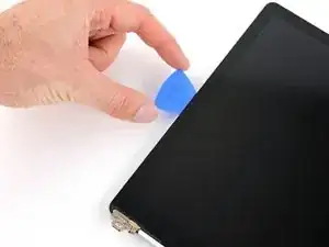
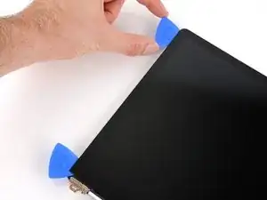
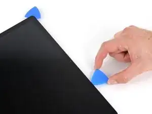
Insert a third opening pick next to the one in the top left corner.
-
Slide your pick toward the middle of the screen to separate the adhesive until you reach the sensor bracket, 69 mm (2.7 in) from the left edge.
-
-
-
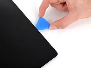
Slide your pick to the top right corner of the screen.
-
Leave this pick in the top right corner to prevent the adhesive from resealing.
-
-
-
Insert a fourth opening pick next to the one in the top right corner.
-
Slide the pick to the bottom right corner to completely separate the right edge adhesive.
-
Leave this pick in the bottom right corner to prevent the adhesive from resealing.
-
-
-
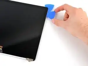
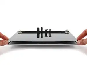
Rotate your screen so the top edge is closest to you.
-
Grab the two opening picks at the top corners of the screen and slide them toward the middle until they're stopped by the sensor bracket.
-
Angle both picks downward so they slide underneath the sensor bracket.
-
Slide the angled picks toward the middle of the screen until the top edge separates from the back cover.
-
-
-
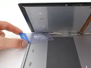
Hold your screen propped up with one hand.
-
With your other hand, use a plastic card to slice the adhesive securing the bottom left and right corners.
-
-
-
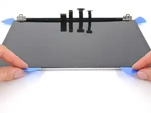
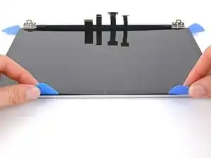
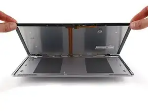
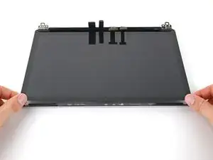
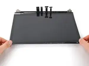
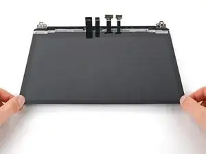
Grab the top corners of the screen and lower it back down flat onto the back cover.
-
Pull the screen away from the hinges and "walk" it side-to-side to separate the remaining adhesive along the bottom edge.
-
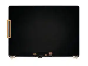
Remove the screen.
-
-
-
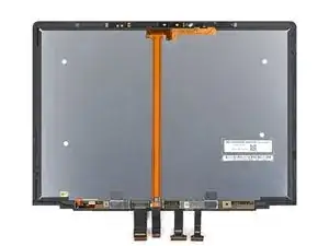
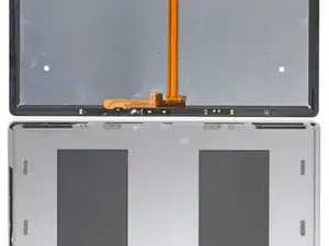
Flip the screen over and lay it glass-side down onto your work surface.
-
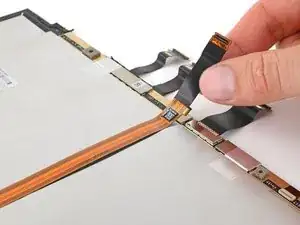
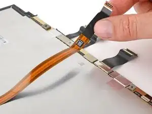
Gently peel up the long ribbon cable.
-
-
-
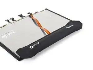
Apply a heated iOpener to the sensor bracket for one minute.
-
The left edge of the sensor bracket is 69 mm (2.7 in) from the edge of the screen.
-
The right edge of the sensor bracket is 84 mm (3.3 in) from the edge of the screen.
-
-
-
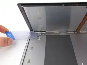
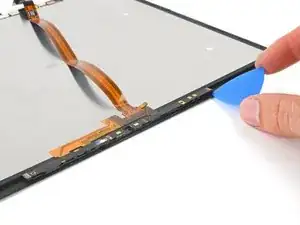
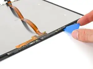
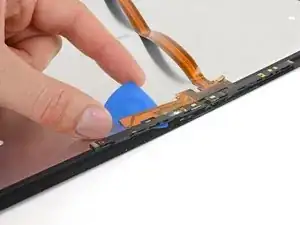
With the top edge of the screen closest to you, insert an opening pick under the right edge of the sensor bracket.
-
Slide your pick under the bracket to separate the adhesive.
-
-
-
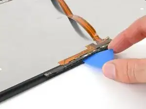
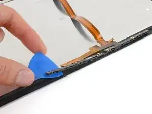
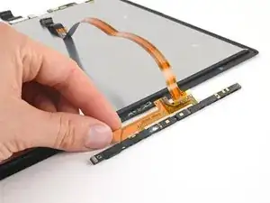
Once you reach the end of the sensor bracket, rotate your opening pick around the left edge.
-
Slide your pick under the section of cable adhered to the screen to separate its adhesive.
-
-
-
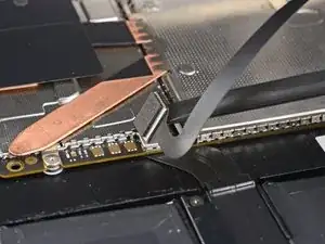
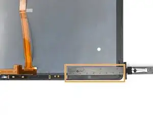
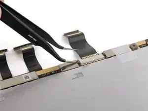
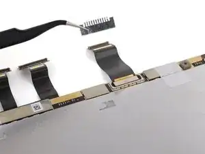
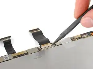
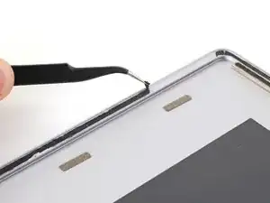
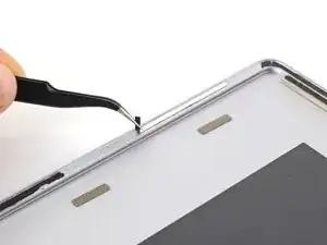
Use one arm of a pair of tweezers to pry up and unclip the shield from the press connector at the base of the screen.
-
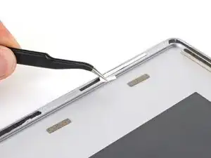
Remove the shield.
-
-
-
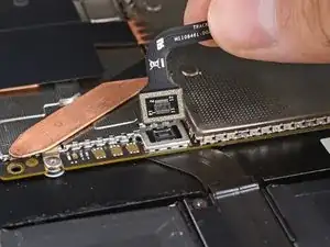
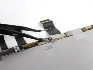
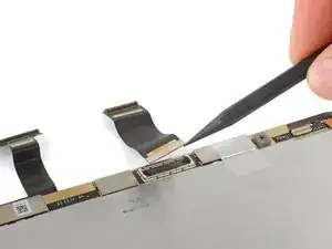
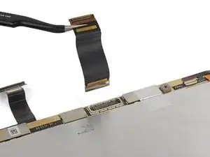
Use the point of your spudger to pry up and disconnect the short display cable from the screen.
-
Remove the cable.
-
-
-
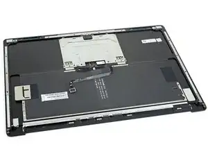
Use tweezers or your fingers to peel and remove any pieces of residual adhesive from the back cover.
-
Clean the perimeter of the back cover with isopropyl alcohol and a lint-free or microfiber cloth.
-
Apply strips of thin double-sided tape to the back cover in the same locations as the old adhesive.
-


Conclusion to be inherited from the live guide.