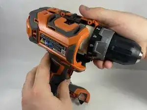
Introduction

Use this guide to replace a damaged or faulty trigger in your Ridgid 860054 Drill.

The drill trigger causes the drill to rotate when pressed. If the trigger is blocked or damaged, it won’t press or it is otherwise faulty, you will be unable to power on and control the drill.

Be sure to cross out all other possibilities on the troubleshooting guide before doing this replacement. It is possible that the drill trigger is still functional. There could be other issues preventing the drill from working instead of the trigger.

Make sure to remove the battery from the drill before beginning the repair.

  1. EMPjkoFDt12nJ6Tx
    EMPjkoFDt12nJ6Tx
    5HsGIHhKto3Z4fUf
    • Using a T10 Torx security bit, remove the ten screws from the housing assembly.

    • All of the casing screws are the same length and require the same bit.

  2. gPmTF2joe1JfuJRa
    gPmTF2joe1JfuJRa
    Sq4uHVlSF1ZQQPLs
    • Separate one half of the drill casing from the other by gently pulling both halves apart.

    • Once one half of the casing is removed, be careful! If the components are directed towards the ground, they could fall out.

  3. J3drUKVEuxsLMJqS
    J3drUKVEuxsLMJqS
    Ex652CQVLvHkpZlO
    5xROgE6JPptAPlvi
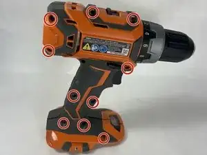
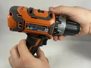
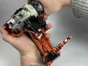
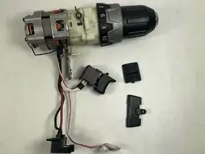
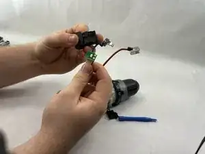
    • Remove the plastic speed switch and forward/reverse switch by softly lifting them from the casing.

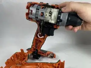
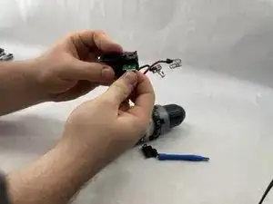
    • Remove the internal components of the drill by lightly pulling on the drill chuck.

    • All of the other electronic components are attached to the chuck, and will come out with it.

  4. Vhw6nwxcLgAFQVFI
    • The main section of the drill should have the trigger, light indicator, and battery prongs all connected via wire. There should be two plastic switches separated from the rest of the body.

  5. gDfc1gWPRYoSuDRk
    gDfc1gWPRYoSuDRk
    DbCBHdQVKdeWIvxK
    AVWxOuK1bWfX3Fis
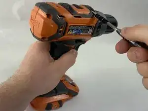
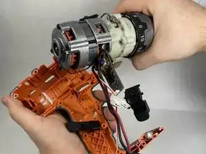
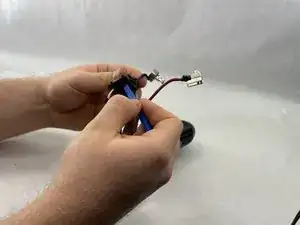
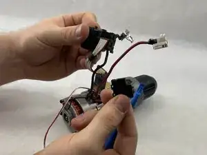
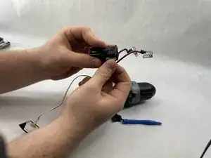
    • Use a thin tool to disconnect the three prongs.

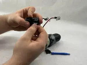
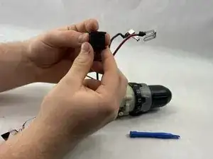
    • Remove the black plastic piece from the trigger body.

    • On the new trigger, follow the same steps as above and remove the cap.

  6. R1BRk6n2CDNcZ3Kl
    R1BRk6n2CDNcZ3Kl
    WbdpuphLNUFEIrEi
    • Remove the trigger circuit from the plastic trigger body.

  7. yULP5uVhmIdEw1ow
    yULP5uVhmIdEw1ow
    lLGC3SUMsqntky2B
    XJdeaZZkTumPZ4Nd
    • Place the circuit into the new trigger and closure.

    • Place the plastic cap back on the trigger to secure the wire.

Conclusion

To reassemble your device, follow these instructions in reverse order.

Ryan Friedman

Member since: 13/03/23

109 Reputation

0 comments