Introduzione
Ogni riparatore deve essere capace di utilizzare un multimetro per eseguire misurazioni di voltaggio, resistenza e test di continuità.
Di seguito le tre funzionalità base di un multimetro.
Per imparare come utilizzare il tuo multimetro per effettuare misurazioni avanzate come corrente e capacità, consulta questa guida.
Strumenti
-
-
Un test di continuità ci dice se due componenti sono connessi elettricamente: se qualcosa è continuo, può essere attraversato liberamente da corrente.
-
Se non c'è continuità vuol dire che c'è un problema da qualche parte nel circuito. Questo può indicare qualunque cosa, da un fusibile bruciato o una saldatura fatta male a un collegamento errato.
-
-
-
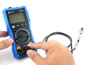
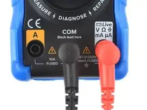
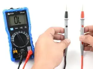
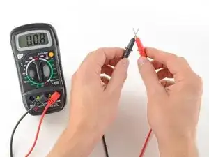
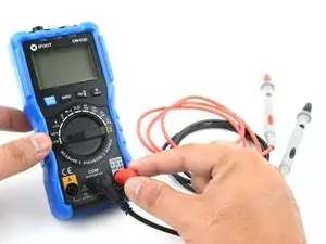
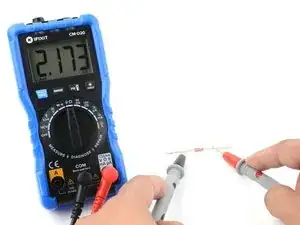
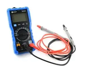
Inserisci il puntale nero nella porta COM sul tuo multimetro.
-
Inserisci il puntale rosso nella porta contrassegnata con un simbolo V (in questo caso, la porta destra).
-
-
-
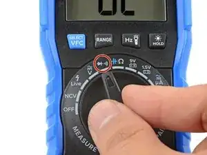
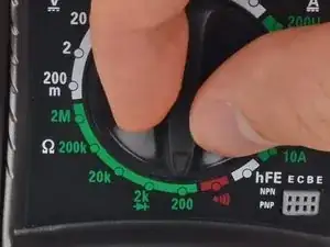
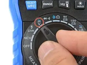
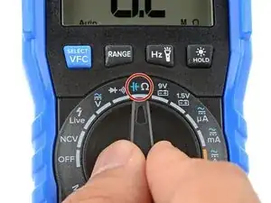
Accendi il multimetro e posiziona il selettore sulla modalità continuità (indicata da un icona a onde simile a quella del WiFi).
-
-
-
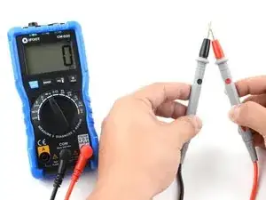
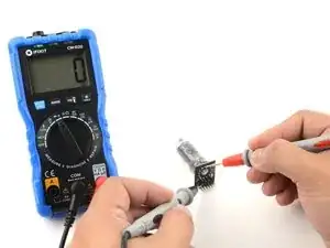
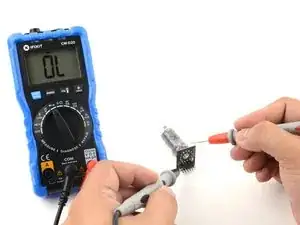
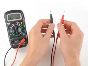
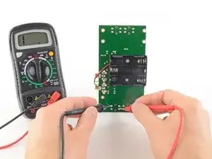
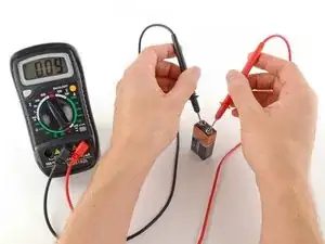
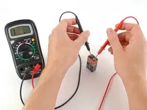
Per completare il test di continuità posiziona i puntali agli estremi del circuito o del componente da testare.
-
Per verificare questo, inverti ciò a cui i puntali sono in contatto e verifica la continuità. Se il multimetro mostra continuità, potrebbe trattarsi di un diodo.
-
-
-
Se il tuo multimetro non ha una modalità dedicata al test della continuità puoi effettuare comunque la prova.
-
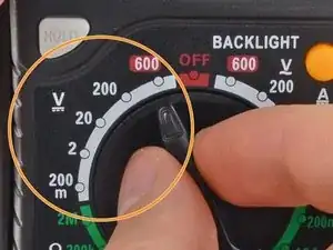
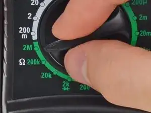
Ruota la manopola sulla modalità di resistenza.
-
Se il tuo multimetro ha la regolazione manuale, impostare la resistenza al livello più basso.
-
-
-
In questa modalità il multimetro invia una piccola corrente attraverso un puntale e misura se e quanta ne viene ricevuta dall'altro puntale.
-
Se i puntali sono connessi - sia tramite un circuito continuo oppure siano connessi direttamente - la corrente li attraversa. Lo schermo mostrerà il valore zero (oppure un numero vicino a zero- in questo caso 0,8). Una resistenza molto bassa indica che il circuito è continuo.
-
Se nessuna corrente viene misurata vuol dire che non c'è continuità. Lo schermo mostrerà OL (open loop).
-
-
-
Per completare il test di continuità posiziona i puntali agli estremi del circuito o del componente da testare.
-
Come prima, se il circuito è connesso lo schermo mostrerà il valore zero ( o un valore vicino allo zero) .
-
Se lo schermo mostra OL (open loop) non c'è continuità: non c'è nessun percorso che la corrente possa attraversare per arrivare all'altro puntale.
-
-
-
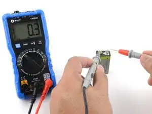
I prossimi quattro passi ti mostreranno come misurare la tensione.
-
Inserisci il puntale nero nel foro COM del tuo multimetro.
-
Inserisci il puntale rosso nella porta contrassegnata con un simbolo V (in questo caso, la porta destra).
-
-
-
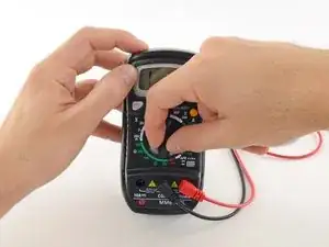
Accendi il multimetro e posiziona il rotore sulla modalità voltaggio DC (indicata da una V con accanto una linea oppure un simbolo come questo ⎓).
-
Ogni impostazione sulla manopola indica la tensione massima che può misurare. Quindi, ad esempio, se prevedi di misurare più di 2 volt ma meno di 20, utilizza l'impostazione a 20 volt.
-
Se non sei certo della tensione che devi misurare parti con la scala più alta.
-
-
-
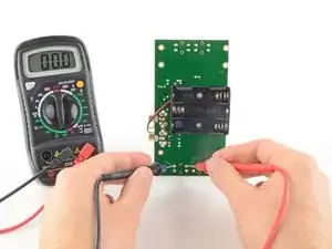
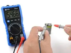
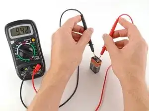
Posiziona il puntale rosso sul terminale positivo e il puntale nero sul terminale negativo. Il multimetro visualizzerà la tensione misurata.
-
Salta il passaggio successivo, che descrive come misurare la tensione utilizzando multimetri a regolazione manuale.
-
-
-
Posiziona il puntale rosso sul terminale positivo e il puntale nero sul terminale negativo. Il multimetro visualizzerà la tensione misurata.
-
Se l'intervallo è stato impostato troppo alto, potresti non ottenere una lettura molto precisa. Qui il multimetro legge 9 volt. Va bene, ma possiamo girare la manopola su una scala più bassa per ottenere una lettura più precisa.
-
Se imposti l'intervallo troppo basso, il multimetro leggerà semplicemente 1 o OL, indicando che è sovraccarico o fuori scala. Questo non danneggerà il multimetro, ma dobbiamo impostare la manopola su una scala più alta.
-
-
-
Per iniziare, assicurati che non ci sia corrente che attraversa il circuito o il componente che desideri misurare. Spegnilo, scollegalo dalla presa e rimuovi eventuali batterie.
-
Inserisci il puntale nero nell'ingresso COM del tuo multimetro.
-
Inserisci il puntale rosso nella porta contrassegnata con un simbolo Ω (in questo caso, la porta destra).
-
-
-
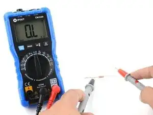
Posiziona un puntale su entrambi i poli del circuito o del componente che vuoi misurare.
-
Se il tuo multimetro non ha la regolazione manuale:
-
Se il multimetro leggerà valori molto vicini allo zero, significa che il range settato è troppo alto. Imposta un range piu basso ruotando il selettore.
-
Se imposti un range troppo basso, il multimetro leggerà 1 oppure OL che indica il sovraccarico oppure il fuori scala. Questo non danneggerà il multimetro ma indica che dobbiamo impostare con il selettore una scala più alta.
-
L'altra possibilità è che il circuito o il componente che stai testando non ha continuità/è interrotto, quindi ha infinita resistenza. Un circuito interrotto segnerà sempre 1 o OL su un test di resistenza.
-