Introduzione

L'accesso diretto al meccanismo di stampa è limitato, che tu debba indagare su un guasto o risolvere un inceppamento di carta particolarmente grave. La rimozione dell'unità scanner semplifica notevolmente questa operazione ed è un requisito preliminare per ulteriori operazioni di smontaggio.

I cavi a nastro sono tutti del tipo push fit. Tira delicatamente ma con decisione per sganciarli dalla presa. Per ricollegarli, spingi semplicemente l'estremità rinforzata del nastro nella presa, assicurandoti che sia orientato correttamente.

  1. otyyhRvNGl5tRegb
    • Potresti rimuovere le cartucce d'inchiostro se stai pianificando uno smontaggio radicale, anche se ciò non è necessario per questa guida. Segui le istruzioni nel Manuale dell'Utente e posizionale in un sacchetto di polietilene, sia per evitare che si asciughino sia per evitare macchie d'inchiostro sulla superficie di lavoro o sui vestiti.

    • Spegni la stampante se è accesa, premendo il pulsante di accensione e attendendo che la spia di alimentazione smetta di lampeggiare. Ora scollega il cavo di alimentazione e il cavo USB (se collegato).

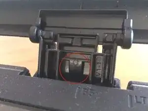
    • Solleva il coperchio dello scanner quanto possibile. Premi il dito al centro di ogni cerniera per staccarla.

  2. aeF25PQWQncr6eLj
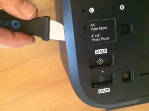
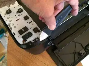
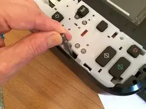
    • Utilizzando un jimmy (o un utensile simile), rilascia le clip intorno al bordo del pannello di controllo, quindi solleva il coperchio.

  3. IhLybZI2WsIauSpX
    • Rimuovi 2 viti a croce da ciascun lato del retro della stampante.

  4. mCMrS1dlEHGpH15f
    mCMrS1dlEHGpH15f
    12LQO5Duwdh4TPoK
    YeJnkRMVBqibvdGU
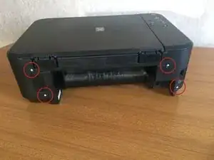
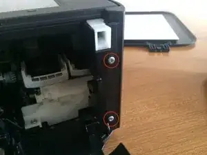
    • Rimuovi le 2 viti a croce dalla parte anteriore della stampante sul lato destro.

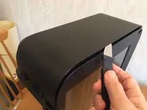
    • Mentre la stampante è in piedi sul lato sinistro, sgancia il pannello laterale destro, prima lungo il bordo superiore e poi nella parte posteriore. Dovrebbe staccarsi completamente ora.

  5. d6cHbmIgbOmHPVwc
    d6cHbmIgbOmHPVwc
    omTMfaWY3iUdnStw
    KqfI4rpw24aS4k6n
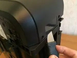
    • Sgancia la parte posteriore del pannello laterale sinistro.

    • Sgancia la parte anteriore del pannello laterale sinistro.

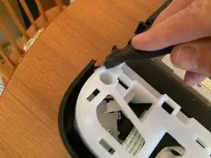
    • Il pannello laterale è ancora trattenuto da una clip nascosta sotto un foro rettangolare vicino al bordo del pannello di controllo. Rilascialo premendoci sopra con la lama di un cacciavite piatto. Il pannello sinistro dovrebbe staccarsi ora.

    Worth noting that the left panel appears to be secured by 3 clips at the bottom edge on the 3650 model, is it the same on this one? Slide a lifter in between the bottom panel and the lower edge of the left side panel to free and it should just lift off.

    Val Allen -

  6. se5N2C6Wuvddn4HJ
    se5N2C6Wuvddn4HJ
    1N26rQBnhuvMSsEg
    JI2Nq6m2416Dbmm5
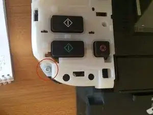
    • Rimuovi una vite dall'angolo anteriore sinistro del pannello di controllo.

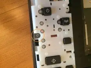
    • Rimuovi una vite dalla parte centrale del lato sinistro del pannello di controllo.

    • Rimuovi una vite dalla parte posteriore del pannello di controllo.

  7. nfV2sZFZrT6xGnaO
    • Solleva il pannello di controllo, facendo attenzione a non forzare il nastro flessibile, che è ancora collegato.

    • Scollega il nastro flessibile.

    How do you disconnect the ribbon cable? Just pull it?

    oluc -

    How to access and replace Ink Absorber

    Graham Bond -

    Hallo, Wirklich den Stecker abziehen ? Ich bekomme das nicht ab ... Hab Angst es zu zerstören

    Heiko Klittich -

    Hello, Are you sure you want to unplug it? I can't get this off... Afraid of destroying it

    The ribbon is reinforced where it enters the connector so no danger of tearing it. Grip it close to the connector and pull quite hard.

    Das Band ist dort verstärkt, wo es in den Stecker eintritt, sodass keine Gefahr besteht, dass es reißt. Fassen Sie es nahe am Stecker und ziehen Sie ziemlich fest.

    Philip Le Riche -

    You should add a photo of the disconnected cable. I have tried to pull the black connector. But it is the part attached to the motherboard

    Mathieu -

    Pull the ribbon not the black connector. See also Riconoscimento e scollegamento dei connettori dei cavi (I no longer have this printer so can't get extra photos. Perhaps you'd like to add one?)

    Philip Le Riche -

  8. OZcWXVUyTbNNRKPN
    OZcWXVUyTbNNRKPN
    1SKUd1kJkWpCSm2C
    • Scollega il nastro del modulo WiFi dalla scheda logica principale.

    • Rimuovi la vite che tiene in posizione la staffa del modulo WiFi e rimuovi insieme la staffa e il modulo.

    • Nota che questa vite è diversa da tutte le altre.

    I seem to have a later version (board is D67 not D38) and the wifi module is to the right of the logic board, not on top, so doesn't need disconnecting to get the scanner off.

    Joffy -

  9. AMIlAinyMs33QxQu
    • Scollega un cavo a nastro largo dalla parte superiore della scheda logica.

    • Scollega un cavo a nastro stretto piegato dall'angolo in basso a sinistra.

    • (Non è necessario scollegare il connettore con 2 fili rossi sul lato sinistro della scheda logica.)

    Unroll the two red wires from the hook.

    Pierre de torcy -

  10. j6ySt2xwKeEYtccj
    j6ySt2xwKeEYtccj
    xCghGtPZs1qyDDH1
    • Rimuovi la vite in alto a sinistra del vetro.

    • Rimuovi la vite in basso a sinistra del vetro.

    • Successivamente solleva delicatamente le due linguette delle viti appena rimosse e scorri l'intero vetro di circa 1/4 di pollice (5 mm) verso sinistra.

    • (Nota: Evita qualsiasi presenza di polvere all'interno dell'unità scanner.)

    • Puoi fermarti qui se non sei interessato alla parte della stampante, o rimettere il vetro e continuare.

  11. jTmBY6fwU2gFXR3g
    jTmBY6fwU2gFXR3g
    ixAJffxMDVM3OAMx
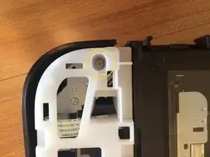
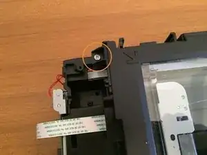
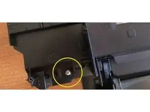
    • Rimuovi una vite dal vano che ospitava il modulo WiFi.

    • Rimuovi la vite dalla parte anteriore sinistra del dispositivo.

  12. VupELfCOtUFBtfgd
    VupELfCOtUFBtfgd
    DslQL5KsyDsyuSHM
    yF5Qo2GPonJYpar1
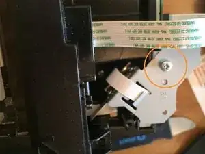
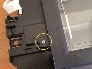
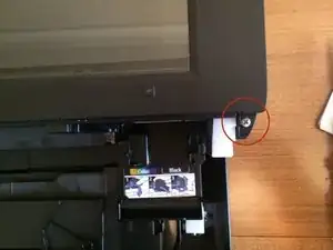
    • Rimuovi una vite dal lato anteriore destro.

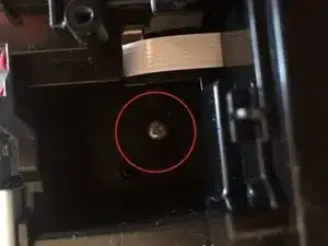
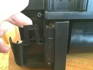
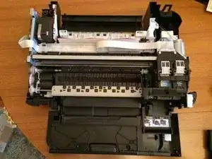
    • Rilascia un fermo sul lato posteriore sinistro del dispositivo (come visto dalla parte posteriore) e solleva l'unità scanner.

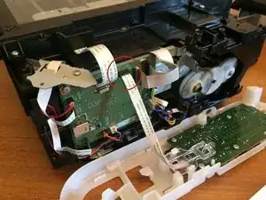
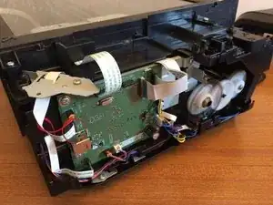
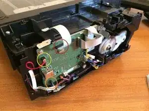
    • Ora potrai vedere il meccanismo di stampa in modo più chiaro e procedere con eventuali ulteriori smontaggi necessari.

    Note: if you want to further disasemble the scanner unit, don’t try to pry it open by force like I just did :-/.

    Instead, gently slide the upper glass pane from right to about 5 mm and it should come loose.

    Please then make sure not to let any dust in of course.

    Vincent Deconinck -

Conclusione

Per rimontare il tuo dispositivo, segui queste istruzioni in ordine inverso.

Philip Le Riche

Membro da: 18/02/14

29996 Reputazione

12 commenti

Very good description. I need to empty my ink collection tank/tray. Once I have removed the scanner assembly as you describe, will I then gain access to theis container? Thanks.

John Stuart -

See link to YouTube video below. You need long tweezers and be careful when replacing the pads as they can drop into the mechanism easily .. which is why I found this tutorial on how to dismantle the printer!

https://m.youtube.com/watch?v=TLN5ALnt73...

Peter King -

Hi. Where inside the printer to look in order to clear the error 5b02_ Thank you!

Horia Morariu -

Hi, how can i clean my ink tank to clear the 5B02 error code? Thank you

francina erasmus -

Habe schön zerlegt, werde sicher zusammenbauen, wollte aber noch wissen warum das Papier im rechten Drittelbereich zerrissen wird.

Muß noch versuchen den Papiereinzug zu putzen bzw. den Fehler zu beheben.

Joksi

joksi -

thank you very much! you saved my workday! i am a girl and i really appreciate so simple manual. i wish every manual was so simple! :)))

PATRICIA -

Well done Patricia! You never need to apologise or anything of the sort for being a girl - girls are often better at this sort of thing as they tend to be more careful whereas boys sometimes rush on in a slapdash manner as if it were a race! Just believe in yourself and don’t be afraid to make mistakes - that’s how you learn - and you’ll soon be an ace fixer!

Philip Le Riche -

Well done explanation. You saved my printer from trash. Unresolved head alignment (tried everything) by opening the printer and perfectly clean the plastic band behind heads (it’s a pace counter in reality), as well as the plastic circle on the side opposite to head rest . were really dirty and giving false positioning to the head. Now works smoothly and precisely as new. Many thanks !

Alberto Lampis -

Thank you! Worked well also with the MG3650S, where you don’t need to do step 8, as the WiFi controller is in the middle-right of the main board.

pmgasser -

Hi, my paper feeder lost all their plastic bands.

But the lower space is too hollow to let me fix it. Is it possible to further disassembly to reach that part?

Or can you think of any workaround to fix that?

Thanks

Wonson -

My MG2260 is unable to find paper in the tray, is there a simple fix

mjpenhey -

Hello everyone and thanks for the very useful guide. My Mg3650 has a paper loading problem, that is, sometimes it is unable to take it, other times it takes it a little crookedly and the paper gets stuck inside the printer... I noticed that the trolley with the two rubberized wheels which is used for pulling the paper in, it doesn't put enough pressure on the paper because I think it has a broken spring... before opening the printer following the guide, can anyone tell me if it is possible to replace or repair the spring? Maybe it's just unhooked but I'll only know when I open it. I'm wondering if any of you have had the same experience. Thank you!

Gian Luca -