Introduzione
Use this guide to disconnect the display and camera cables in your MacBook Air 15" 2023.
-
-
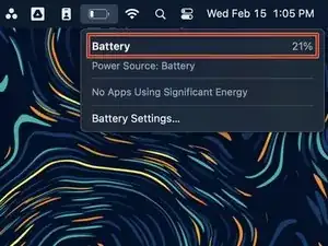
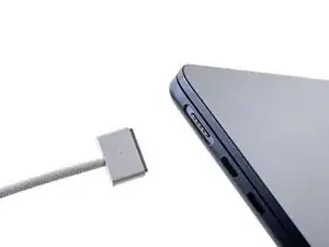
Unplug all cables and fully power off your MacBook.
-
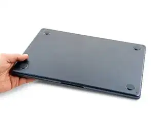
Close the display and lay your MacBook upside down. Keep your laptop closed until you've physically disconnected the battery.
-
-
-
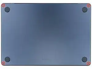
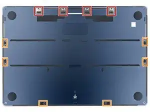
Use a P5 pentalobe screwdriver to remove the four 6.4 mm‑long screws securing the lower case.
-
-
-
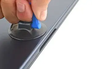
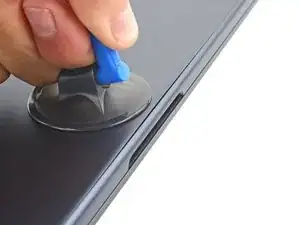
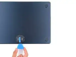
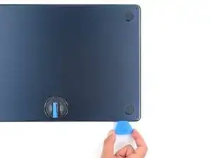
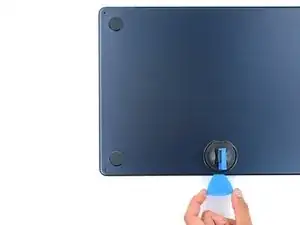
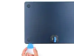
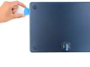
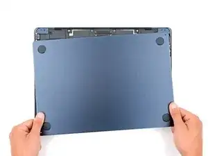
Apply a suction handle to the center of the lower case's front edge.
-
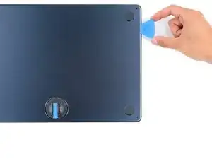
Pull up on the suction handle to create a gap between the lower case and the frame.
-
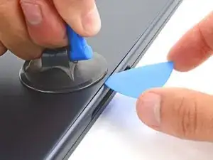
Insert an opening pick into the gap.
-
-
-
Slide the pick to the bottom right corner to release the first clip.
-
Slide the pick around the corner and up the right edge to release the next two clips.
-
-
-
Insert the opening pick in the original gap created with the suction handle.
-
Slide the opening pick to the bottom left corner and up the left edge to release the three remaining snapping clips.
-
-
-
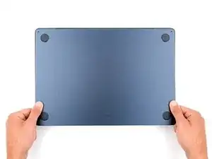
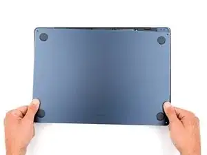
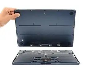
Keep the lower case flat and firmly pull it straight away from the back edge, one corner at a time, to disengage the sliding tabs.
-
-
-
Remove the lower case.
-
Set the lower case in place and align the sliding tabs with the screw heads they slide over. Press down and slide the lower case toward the back edge to engage the tabs—it'll stop sliding as the tabs engage.
-
Once the lower case is flush with the frame, press down firmly along the perimeter to engage the six snapping clips.
-
-
-
Use blunt nose tweezers or your fingers to remove the piece of tape covering the battery connector cover.
-
-
-
Use a T3 Torx screwdriver to remove the two 1.5 mm‑long screws securing the battery connector cover.
-
Remove the cover.
-
-
-
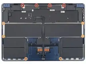
Use a T3 Torx screwdriver to remove the following screws:
-
Two 2.6 mm‑long screws securing the left hinge cover
-
Two 1.5 mm‑long screws securing the speaker cable cover
-
-
-
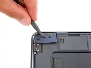
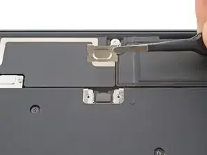
Insert the point of a spudger into one of the left hinge cover's screw holes.
-
Push the hinge cover away from the back edge to dislodge it.
-
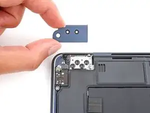
Remove the hinge cover.
-
-
-
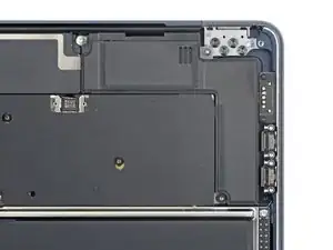
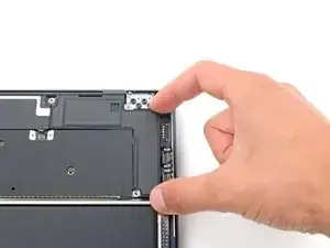
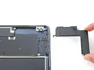
Use a T5 Torx screwdriver to remove the two screws securing the top edge of the right speaker:
-
One 2.7 mm‑long screw
-
One 5.5 mm‑long screw
-
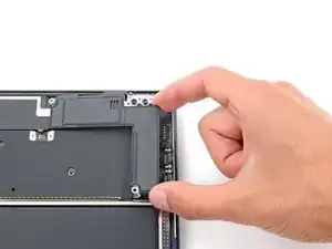
Use a T6 Torx screwdriver to remove the 3.5 mm‑long screw securing the bottom edge of the speaker.
-
-
-
Use a T3 Torx screwdriver to remove the following screws:
-
Two 2.6 mm‑long screws securing the right hinge cover
-
Two 1.5 mm‑long screws securing the speaker cable cover
-
-
-
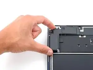
Insert the point of a spudger into one of the right hinge cover's screw holes.
-
Push the hinge cover away from the back edge to dislodge it.
-
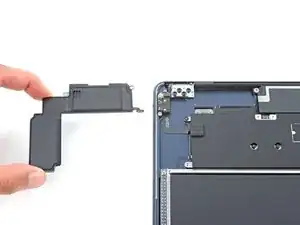
Remove the hinge cover.
-
-
-
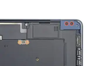
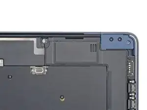
Use a T5 Torx screwdriver to remove the two screws securing the top edge of the left speaker:
-
One 2.7 mm‑long screw
-
One 5.5 mm‑long screw
-
Use a T6 Torx screwdriver to remove the 3.5 mm‑long screw securing the bottom edge of the speaker.
-
-
-
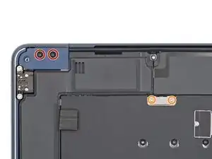
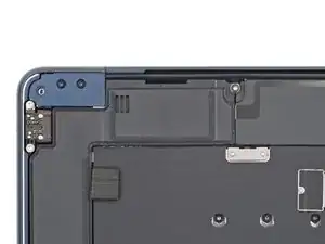
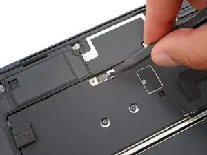
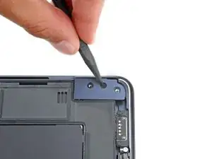
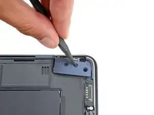
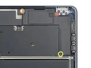
Use a T3 Torx screwdriver to remove the two 1.5 mm‑long screws securing the antenna cables cover.
-
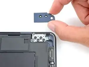
Remove the cover.
-
-
-
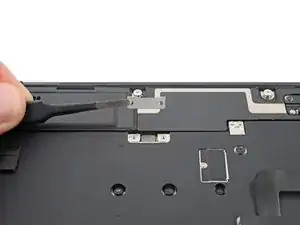
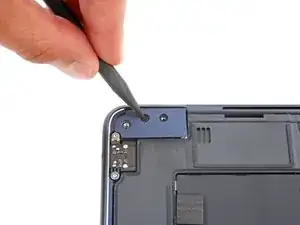
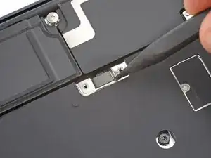
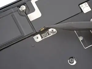
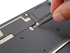
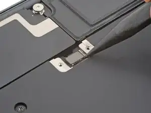
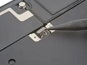
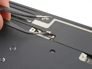
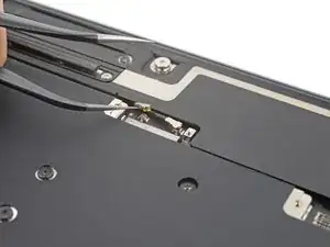
Insert one arm of a pair of angled tweezers under the metal neck of one of the antenna connectors and lift straight up to disconnect it.
-
Disconnect the other antenna.
-
-
-
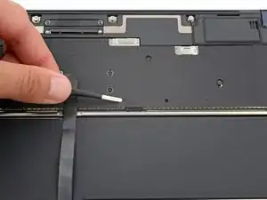
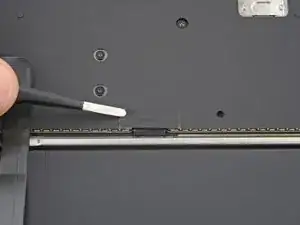
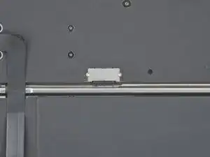
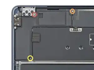
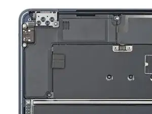
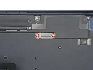
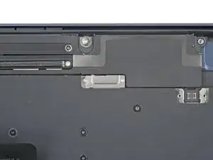
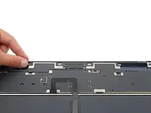
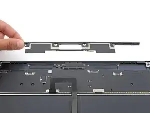
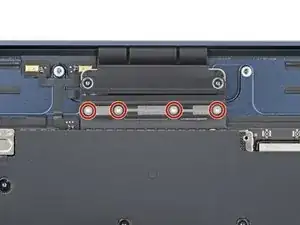
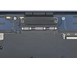
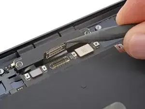
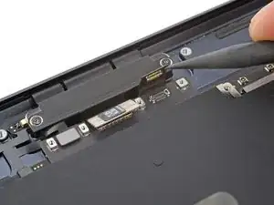
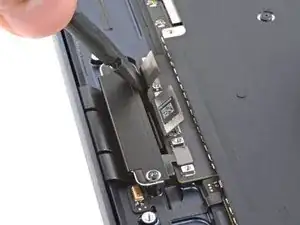
Use a T3 Torx screwdriver to remove the four 1.5 mm‑long screws securing the display and camera cables cover.
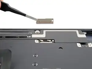
-
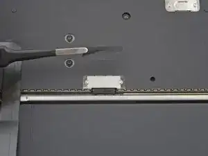
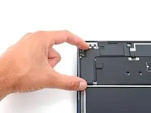
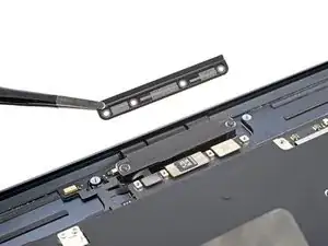
Remove the cover.
-
-
-
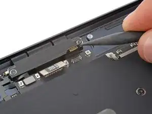
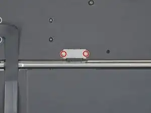
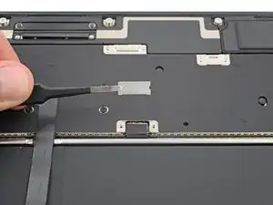
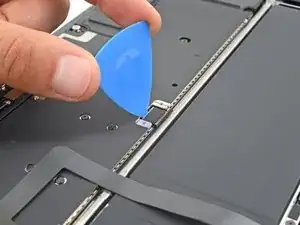
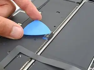
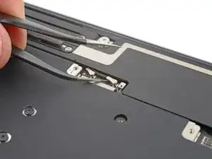
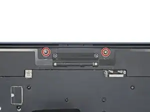
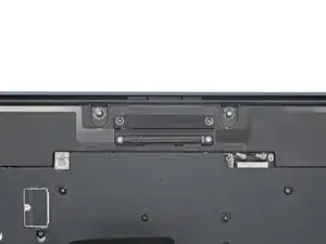
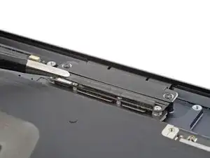
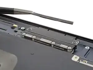
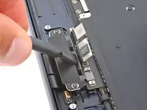
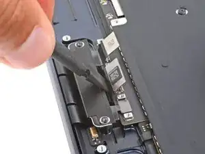
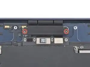
Use a T3 Torx screwdriver to remove the two 2.8 mm‑long screws securing the display and camera cables to the frame.
-

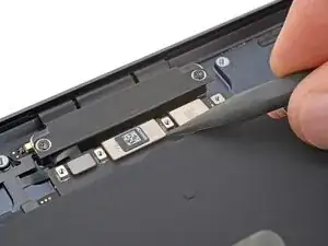
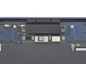
To reassemble your device, follow these instructions in reverse order.
