Introduzione
This guide demonstrates how to remove the logic board in your Google Pixel 7a.
-
-
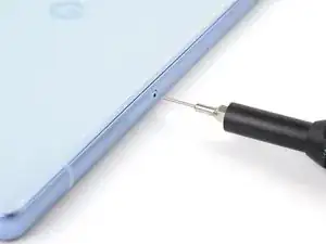
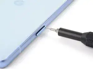
Insert a SIM eject tool, bit, or straightened paper clip into the SIM card tray hole.
-
Press the SIM eject tool into the hole to eject the SIM card tray.
-
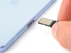
Remove the SIM card tray.
-
-
-
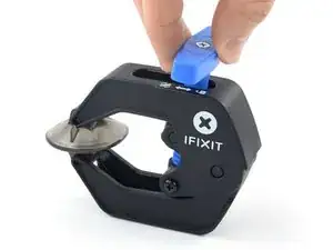
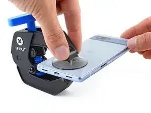
Pull the blue handle backward to unlock the Anti-Clamp's arms.
-
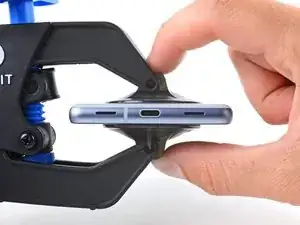
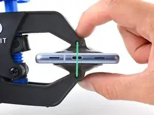
Slide the arms over the bottom edge of the phone, with one suction cup on the rear cover and one on the screen.
-
Squeeze the cups together to create suction.
-
-
-
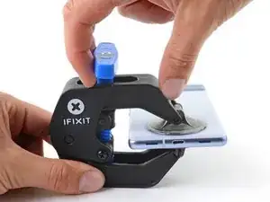
Pull the blue handle forward to lock the arms.
-
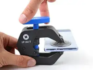
Turn the handle clockwise one full turn (360 degrees), or until the suction cups begin to stretch.
-
As the cups stretch, make sure they stay aligned with each other. If they keep slipping, remove the Anti-Clamp and apply tape for the cups to stick to.
-
-
-
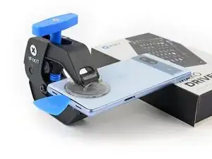
Place an object under your phone so it rests level while between the Anti-Clamp's arms.
-
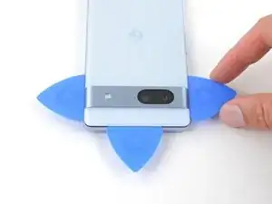
Wait one minute, or until the adhesive separates, for a gap to form along the bottom edge of the phone.
-
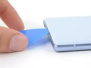
Insert an opening pick into the gap between the rear cover and the frame.
-
Remove the suction cups from the phone using their pull-tabs and set the Anti-Clamp aside.
-
-
-
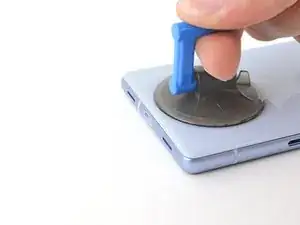
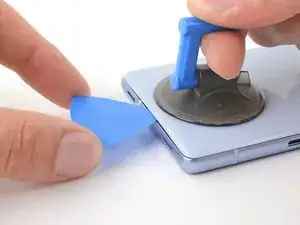
Apply a suction handle to the center of the bottom edge of the rear cover.
-
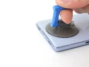
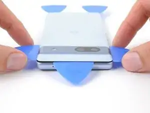
Pull up on the suction handle with a strong, steady force until a gap forms between the rear cover and frame.
-
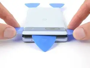
Insert the tip of an opening pick into the gap.
-
Remove the suction handle.
-
-
-
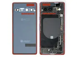
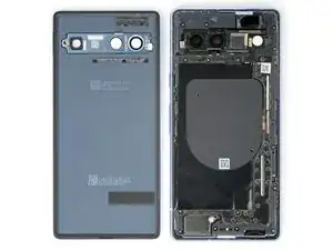
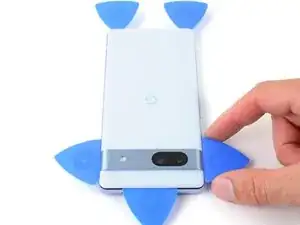
The rear cover is secured with adhesive around the perimeter of the frame and near the cameras. Use this picture as a reference while you slice the adhesive.
-
-
-
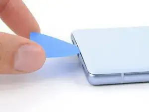
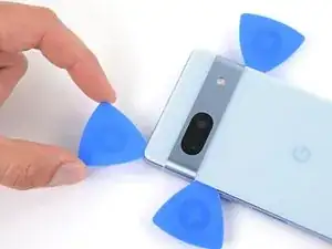
Angle the opening pick upward so the tip faces away from the frame.
-
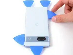
Slide your pick to the bottom left corner of the rear cover.
-
Leave this pick in place to prevent the adhesive from resealing.
-
-
-
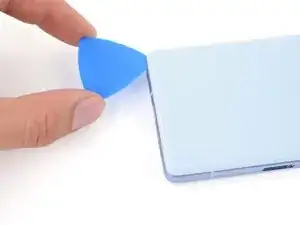
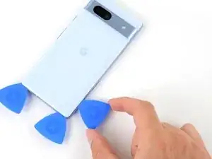
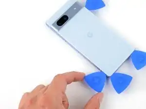
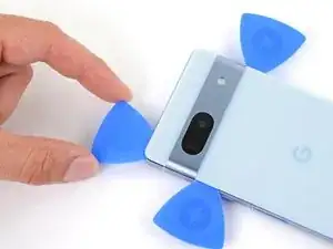
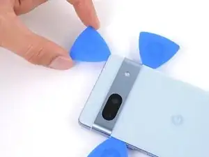
Insert a second opening pick in the bottom left corner.
-
Slide the new pick to the bottom right corner of the rear cover to separate the bottom edge adhesive.
-
Leave this pick in place to prevent the adhesive from resealing.
-
-
-
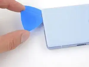
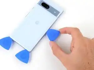
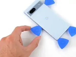
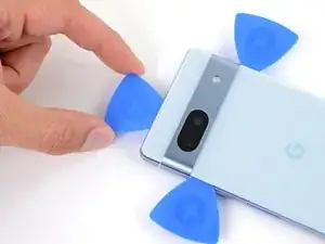
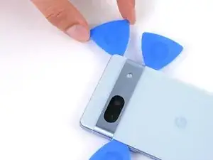
Insert a third opening pick in the bottom right corner of the rear cover.
-
Slide your pick up the right edge of the rear cover to separate its adhesive. Stop when you reach the camera bar.
-
Leave this pick in place to prevent the adhesive from resealing.
-
-
-
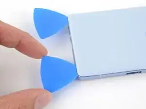
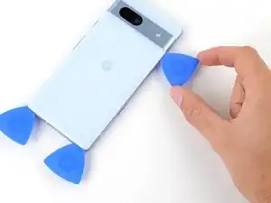
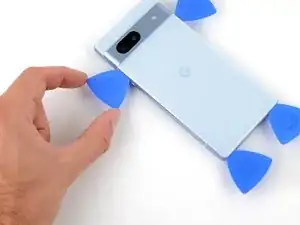
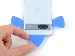
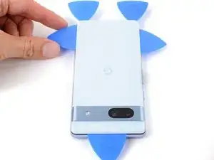
Insert a fourth opening pick in the bottom left corner of the rear cover.
-
Slide your pick up the left edge of the rear cover to separate the adhesive. Stop when you reach the camera bar.
-
Leave this pick in place to prevent the adhesive from resealing.
-
-
-
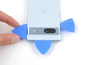
Insert a fifth opening pick in the top left corner of the rear cover between 8 mm and 10 mm (0.3–0.4 in) deep, or just over halfway between the tip of the pick and the iFixit logo.
-
Slide your pick halfway across the top edge to separate the antenna bracket adhesive. Stop at the halfway point along the top edge.
-
-
-
Pull your opening pick out to a depth of 3 mm.
-
Slide your pick to the top right corner to slice the rest of the top edge adhesive.
-
-
-
Roll the top edge pick so its flat edge is under the rear cover.
-
Roll the picks on each side of the camera bar so their flat edges are under the camera bar.
-
-
-
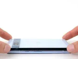
Use the opening picks under the camera bar to pry the top edge of the rear cover from the frame.
-
Pry back and forth until the camera bar loosens.
-
-
-
Slide the opening picks from the camera bar down the long edges of the rear cover to separate any adhesive that may have resealed.
-
-
-
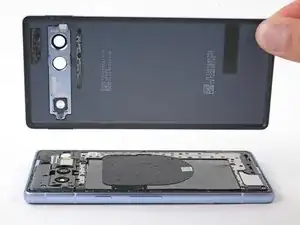
Remove the rear cover.
-
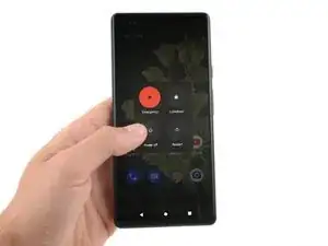
Now is a good time to test your phone before sealing it up. Power it on and check that it works. Power it back down before you continue reassembly.
-
Follow this guide to apply new adhesive and install your rear cover.
-
-
-
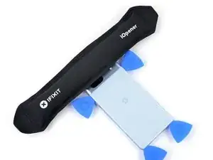
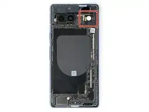
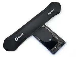
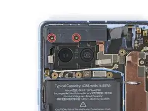
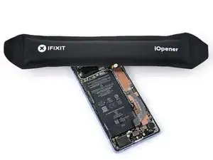
Apply a heated iOpener to the flash unit for one minute to soften the adhesive securing it to the logic board cover.
-
-
-
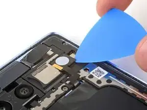
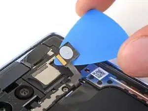
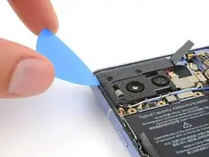
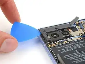
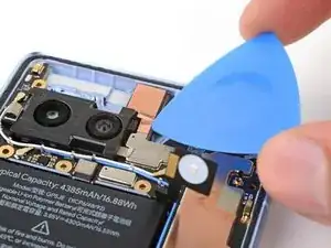
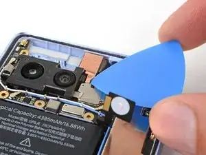
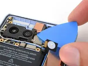
Slide your pick under the right edge of the flash to separate the adhesive securing it to the cover.
-
-
-
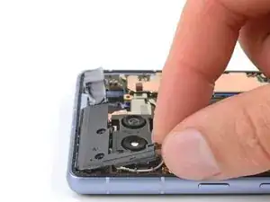
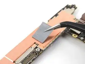
If the copper tape lifted away with the flash, use tweezers or your fingers to remove the black foam residue from the logic board cover.
-
-
-
Apply a heated iOpener to the underside of the flash for one minute.
-
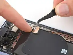
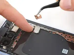
Hold the neck of the flash cable steady and use tweezers to peel and remove the copper tape from the flash unit.
-
-
-
Make sure the small foam spacer is still in the middle of the flash recess in the logic board cover. If not, stick it back to the middle.
-
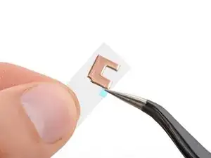
Peel the copper tape from the large adhesive liner.
-
Place the copper tape face-down onto the flash, with the cutout toward the neck of the cable.
-
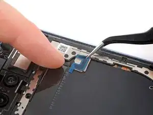
Remove the blue liner to expose the adhesive.
-
Press the flash into place.
-
-
-
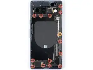
Use a T3 Torx driver to remove the thirteen 4.3 mm 3IP Torx Plus screws securing the logic board cover.
-
Use a T2 Torx driver to remove the 1.5 mm 1IP Torx Plus screw securing the right edge of the cover.
-
-
-
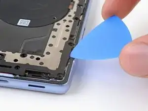
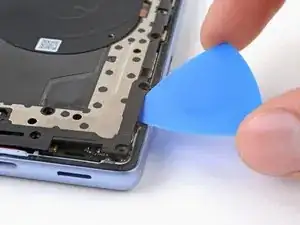
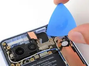
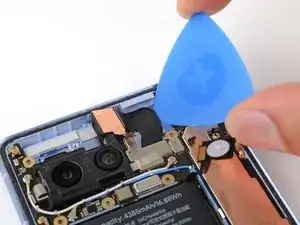
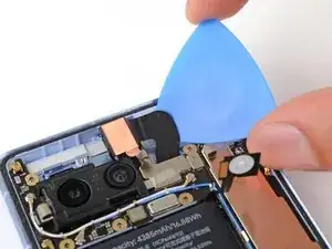
Insert an opening pick between the bottom right corner of the logic board cover and the frame.
-
Pry up to release the clip securing the cover.
-
-
-
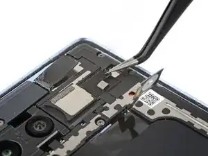
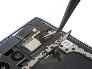
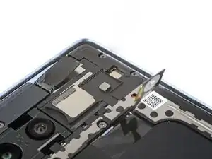
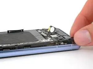
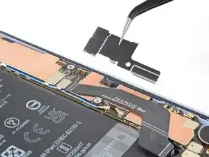
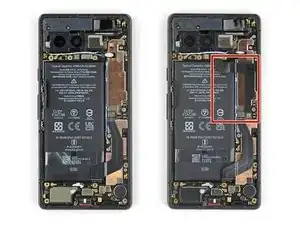
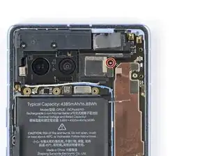
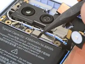
Use your T2 Torx driver to remove the 1.5 mm 1IP Torx Plus screw securing the connector cover.
-
Use tweezers or your fingers to remove the cover.
-
-
-
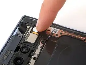
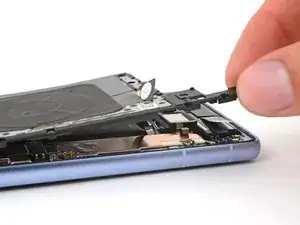
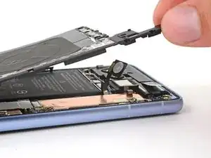
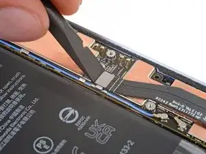
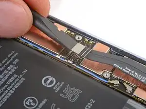
Insert the flat end of a spudger under the top edge of the battery press connector.
-
Pry straight up to disconnect the battery press connector.
-
-
-
Use your T3 Torx driver to remove the 4.3 mm 3IP Torx Plus screw securing the earpiece speaker to the frame.
-
-
-
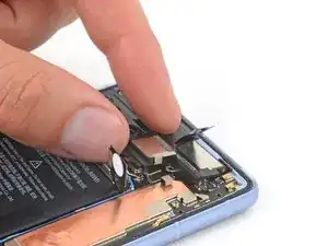
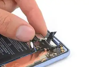
Lift the bottom edge of the earpiece speaker upward.
-
Pull the speaker toward the bottom of the phone to free the red gasket from its cutout in the frame.
-
Remove the speaker.
-
-
-
Use your T3 Torx driver to remove the two 4.3 mm 3IP Torx Plus screws securing the antenna housing to the frame.
-
-
-
Insert an opening pick between the top left corner of the antenna housing and the frame.
-
Pry up to release the clips securing the housing.
-
-
-
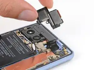
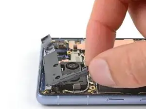
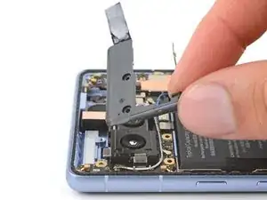
Lift the bottom leg of the antenna housing and pull the top edge out from the frame.
-
Remove the housing.
-
-
-
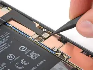
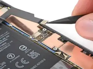
Verizon models: Use the point of your spudger to pry up and disconnect the 5G mmWave press connector.
-
-
-
Apply a heated iOpener to the front-facing camera for one minute to soften the copper tape adhesive.
-
-
-
Insert the tip of an opening pick under the front-facing camera's copper tape.
-
Slowly peel up the tape from the logic board.
-
-
-
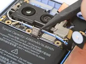
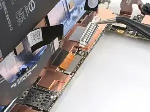
Insert the tip of your opening pick between the right edge of the front-facing camera cable and the frame.
-
Slide your pick underneath the cable to separate the adhesive securing it to the frame.
-
-
-
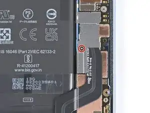
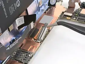
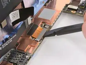
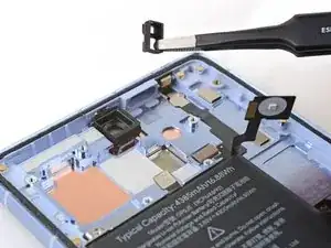
Use the point of a spudger or your fingernail to pry up and disconnect the press connector just above the battery.
-
-
-
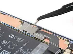
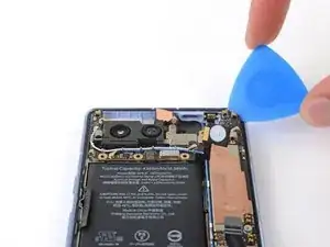
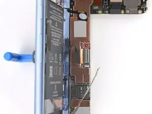
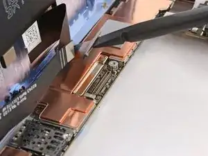
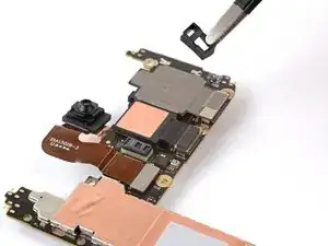
Insert your opening pick between the top right edge of the logic board and the frame.
-
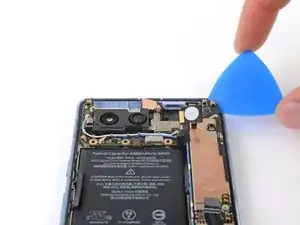
Pry up to free the logic board from its recess.
-
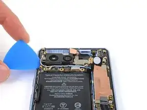
Insert your pick in the gap near the white antenna cable and pry up the top left edge of the logic board.
-
-
-
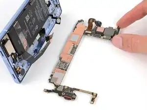
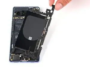
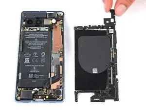
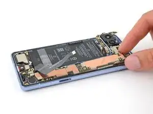
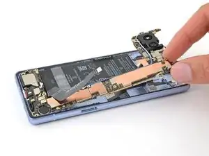
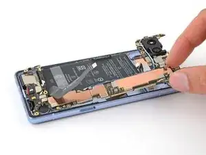
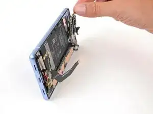
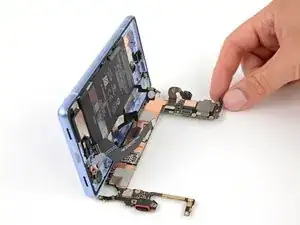
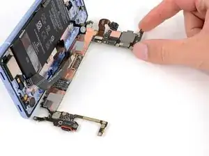
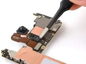
Lift the top edge of the logic board from the frame.
-
Pull the top edge of the logic board to the right of the frame so the cutouts of the board lift over the vibration motor and protrusions in the frame.
-
As you pull, guide the charging port out of its recess in the frame.
-
-
-
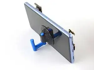
Apply your suction handle to the left side of the screen with the handle facing down.
-
Prop up the phone so it stands upright.
-
Tilt the logic board down and lay it flat. Move any cables out of the way, if necessary.
-
-
-
Use your T3 Torx driver to remove the 2 mm 3IP Torx Plus screw securing the screen connector cover.
-
Remove the cover.
-
-
-
If the front sensor rubber gasket stayed on the frame or became misaligned, remove it and set it aside.
-
-
-
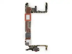
If you're reusing your logic board and the thermal pad is damaged, remove the old thermal pad, clean the surface, and apply a new one.
-
If you have a new logic board and it doesn't come with a thermal pad pre-installed, apply the new thermal pad now.
-


To reassemble your device, follow these instructions in reverse order.