Introduzione

Follow this guide to replace the headstraps in your HTC Vive XR Elite battery cradle.

If your battery is swollen, take appropriate precautions.

  1. hnuvnhyLbDuUMlEV
    • Before starting this repair, discharge the batteries in your headset below 25%. A charged battery may leak dangerous chemicals or catch fire if damaged.

    • Playing Half Life: Alyx will do the trick!

    • The Vive XR Elite has a proximity sensor that puts the headset in standby mode to save battery when it isn't in use. To drain the battery faster you'll need to use the headset.

  2. bjdKIqZEAJNajlep
    bjdKIqZEAJNajlep
    3VjJPLXEBPp4fbyY
    • Disconnect the USB-C power cable.

  3. djQJRxo1UMDJPChO
    djQJRxo1UMDJPChO
    KnkAiqJqPWDQIDkm
    nbcyDDyYAo5yjbfW
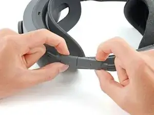
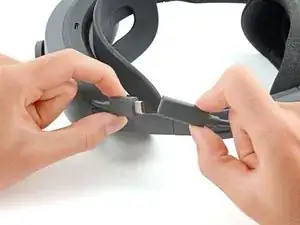
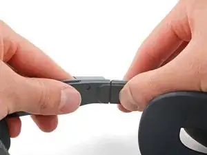
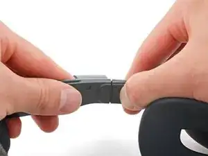
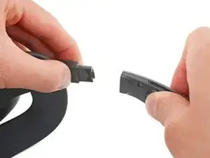
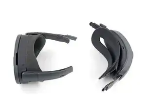
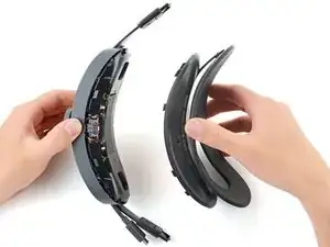
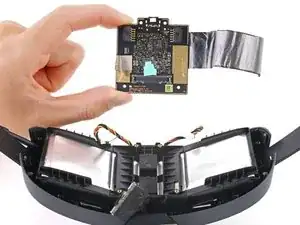
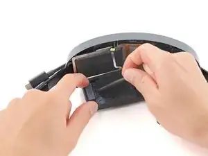
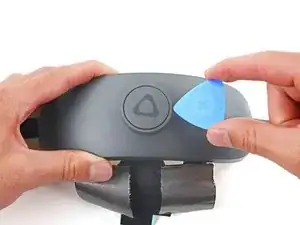
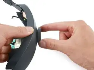
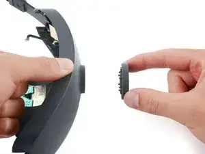
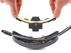
    • Press the release button on the right battery cradle temple slot.

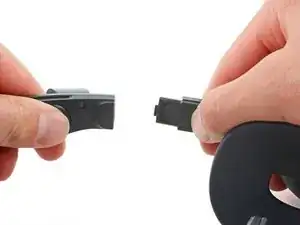
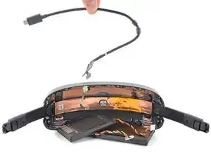
    • Pull the battery cradle away from the right temple slot to disconnect it.

  4. bIiBBtIfTRCUuMrA
    bIiBBtIfTRCUuMrA
    QxUyfeDH6mhxPkIj
    6Q3eGtEXZUOciDtU
    • Repeat the previous step for the left temple slot.

  5. VUFb3hOjRuSUD3ZX
    • Separate the headset and battery cradle.

  6. JkLDTyy2GJaDTsqp
    JkLDTyy2GJaDTsqp
    yfGyv651lc3SLes4
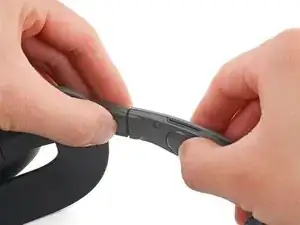
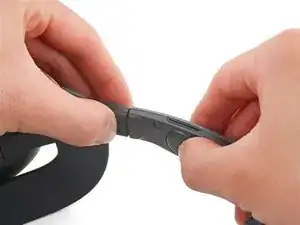
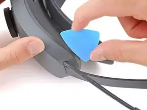
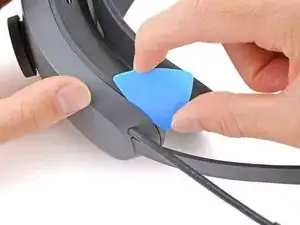
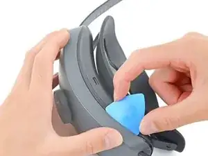
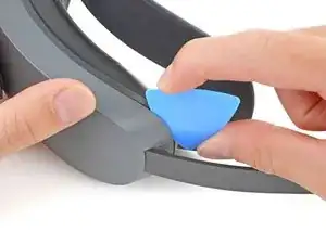
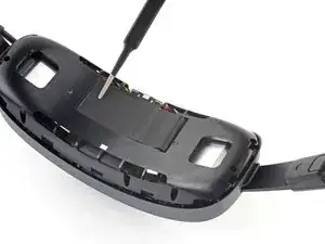
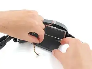
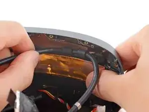
    • Insert a long edge of an opening pick in the gap between the two halves of the battery cradle, near the USB-C cable.

  7. 53KdYpfvCTtiPMs3
    53KdYpfvCTtiPMs3
    E2T5XEJSHQEVpZTw
    VSOtQMEoMH2taqIE
    • Slide the opening pick along the top edge of battery cradle to release its plastic clips.

  8. QqfDIfD2yoSPNblN
    QqfDIfD2yoSPNblN
    2tCBdfJQgMMKREcH
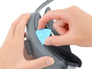
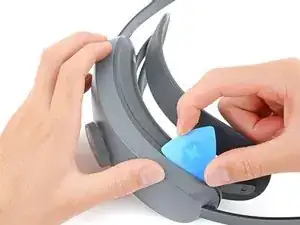
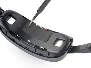
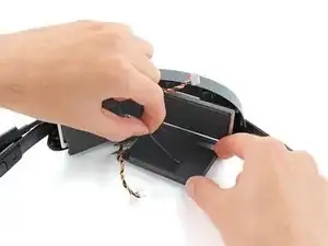
    • Flip the battery cradle over.

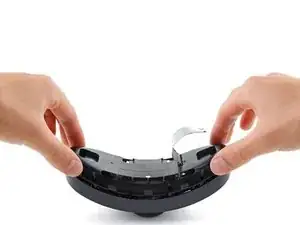
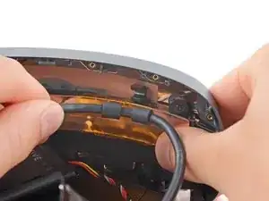
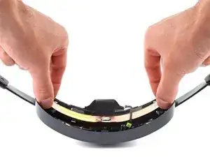
    • Insert the long edge of an opening pick in the gap between the two halves of the battery cradle.

  9. r1vFbNabl6C1t5p6
    r1vFbNabl6C1t5p6
    hj6EhnXvbKRxhHor
    5itJJgdr1Igk42NA
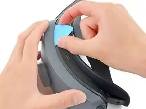
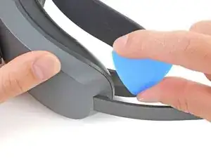
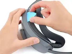
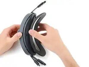
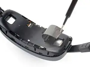
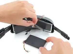
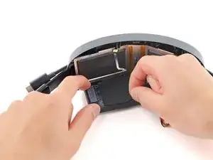
    • Slide the opening pick along the bottom edge of battery cradle to release its plastic clips.

  10. IpauSJFLpXcL1xAU
    IpauSJFLpXcL1xAU
    5LlEATEHYNWSSPiW
    • Pull apart the two halves of the battery cradle to completely separate them.

  11. lfAGD5Zppv5wylYr
    lfAGD5Zppv5wylYr
    3YJSURX6l4ahc4yk
    V2KZqgEQ61rF2Tsv
    • Use tweezers to peel back the graphite thermal tape covering the inner plastic frame.

    • If the tape tears a little, don't worry! During reassembly, stick it back in its original place as if it were still one piece

  12. 3TbRCHRBJ4ENNGIk
    3TbRCHRBJ4ENNGIk
    V3vPHokOjk4NqJOB
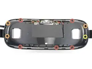
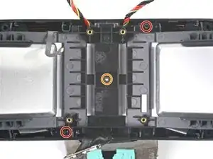
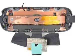
    • Use a T5 Torx screwdriver to remove the nine screws securing the inner plastic frame:

    • Five 11.8 mm-long screws

    • Three 5.6 mm-long screws

    • One 5.6 mm-long screw

    • This screw is covered by a piece of black plastic tape. Use tweezers to remove it before unscrewing.

    • Throughout this repair, keep track of each screw and make sure it goes back exactly where it came from.

  13. ySlxRdG1nMKOBNiE
    ySlxRdG1nMKOBNiE
    2f1b1okGB5jmAFPt
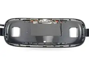
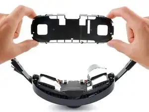
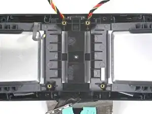
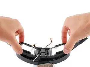
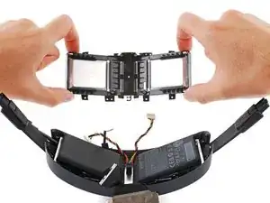
    • Remove the inner plastic frame, making sure to thread the graphite thermal tape through it.

  14. BrLecUVfEWLui1Zq
    BrLecUVfEWLui1Zq
    r61qUMB5SfIUSBPZ
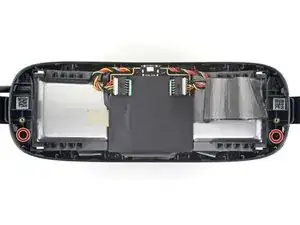
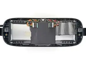
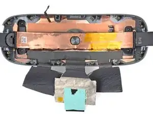
    • Use a T5 Torx screwdriver to remove the two 5.6 mm-long screws securing the headstrap clips.

  15. XkgoYT5SFcBcBI6Q
    XkgoYT5SFcBcBI6Q
    qSChjvaLYdfSSwvJ
    shhZ3w4B5hgssOGO
    • Use tweezers to remove the left and right headstrap clips.

  16. FYXTJpRm5u6TcalO
    FYXTJpRm5u6TcalO
    hQACMraJeBIyGU13
    UultEORTBqv3mEKD
    • Use tweezers or your fingers to peel back the thermal pad covering the battery board.

    • Work slowly to avoid tearing the thermal pad.

  17. uXHDaDjEIIXcm6SS
    uXHDaDjEIIXcm6SS
    lpXAcivdbjT2YvTG
    LrgHTRhtkVj1QeUe
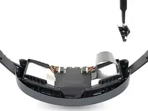
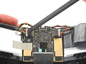
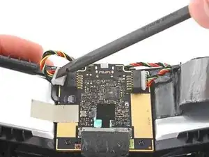
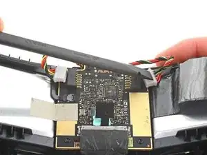
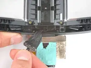
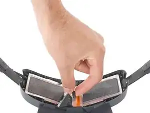
    • Use the flat end of a spudger to push the left and right battery cell connectors out of their respective sockets.

  18. K4It4WfVxhQWW4kt
    K4It4WfVxhQWW4kt
    6mpBWab1cTkZGlj5
    JHV5DWRtXLwXoFxs
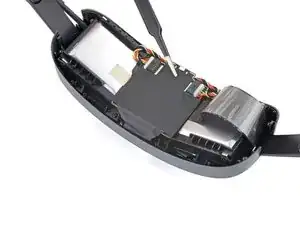
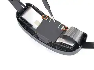
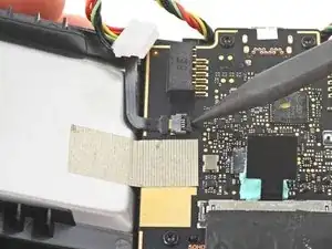
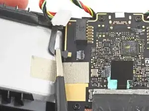
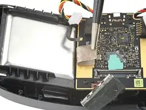
    • Use the point of a spudger to flip up the locking flap on the power LED ZIF connector.

    • Use tweezers or your fingers to disconnect the power LED cable.

    • During reassembly, slide the cable into the connector and close the locking flap. If the cable is getting stuck, gently remove it and realign it before trying again.

  19. sTQhdfyb2RRecO4X
    sTQhdfyb2RRecO4X
    wkx2Xp52rveHrvVA
    • Pull the black tab straight up on the USB-C power cable to disconnect it.

    • During reassembly, align the cable directly over the connector and press straight down to reconnect it.

  20. DsHYOkukfNXUiTAN
    DsHYOkukfNXUiTAN
    wyu5nMpTrcw12wq5
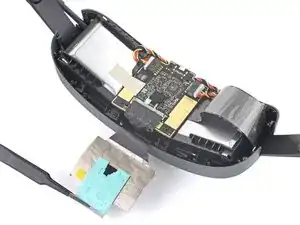
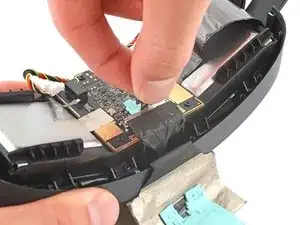
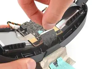
    • Use tweezers or your fingers to peel the conductive tape away from the front metal battery enclosure.

  21. NVZuOEXvqXes2BaF
    NVZuOEXvqXes2BaF
    5qtQyokSMLwOSKnS
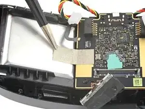
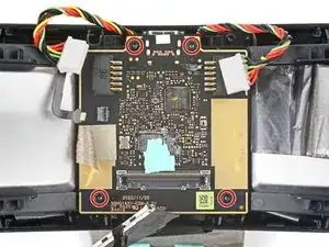
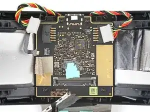
    • Use a T5 Torx screwdriver to remove the four 4.1 mm-long screws securing the battery board.

  22. TjIu2ovOVGwuQmWl
    TjIu2ovOVGwuQmWl
    4BJewj5VEVJjCqLP
    • Remove the battery board.

  23. lcEZ5KZhtixOD3TH
    lcEZ5KZhtixOD3TH
    fnx4PJ6E5hWJBNmw
    • Use a T5 Torx screwdriver to remove the three screws securing the front metal battery enclosure:

    • Two 11.8 mm-long screws

    • One 4.8 mm-long screw

  24. XEnQOMiPexKKZQch
    XEnQOMiPexKKZQch
    NhcXoqogKRUvcLmL
    • Slide the USB-C power cable to the left to unclip it.

  25. sg5X5ZeXpBhAOOdU
    sg5X5ZeXpBhAOOdU
    UIOEagRSbGyJ65WL
    • Remove the front metal battery enclosure.

  26. TpiReGeaNtHGQwBx
    • Stand the battery cradle upright so the battery cells can fold flat on your work surface.

  27. j5NcBSWapmQpCgjp
    j5NcBSWapmQpCgjp
    nnw6NRCYDglUyE1N
    rQsagn1HR2kiHEAU
    • Don't try to fully remove the batteries yet, as they're still attached to the cradle with graphite thermal tape.

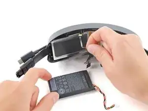
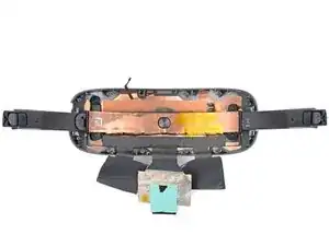
    • Peel off the graphite thermal tape covering the right battery cell.

    • Remove the right battery cell.

  28. uvlNcMZmkHbPgEnw
    uvlNcMZmkHbPgEnw
    TeEvb5SVlQJHoEaf
    y6CQq2Q22gGRDZVd
    • Repeat the previous step for the left battery cell.

  29. 3EdOF5C66xw1hmAH
    3EdOF5C66xw1hmAH
    UGNx6xTquQHSYLyI
    • Grip the center plastic screw spacer with your fingers.

    • Remove the rear metal battery enclosure.

  30. JWo34DUOVLJOUNSl
    JWo34DUOVLJOUNSl
    laS6yLMtgvNUX3mv
    Z5wYyIvUmgCMwTDq
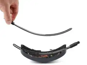
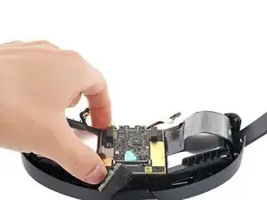
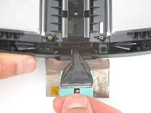
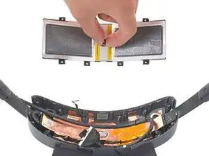
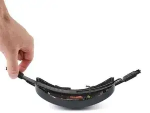
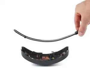
    • Hold one end of the USB-C power cable and pull it straight back to unclip it.

    • Remove the USB-C power cable.

  31. eSib1mdH3VNBeydX
    eSib1mdH3VNBeydX
    A3CBkc3ooVdEgjFw
    avqQmQVTeIDLnjm4
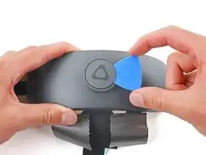
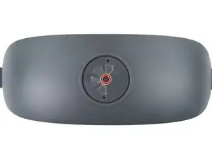
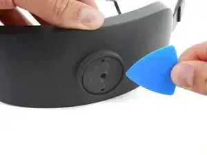
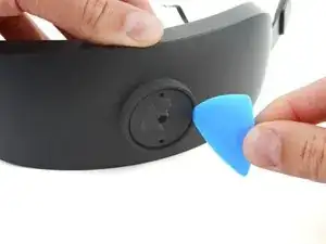
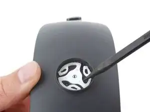
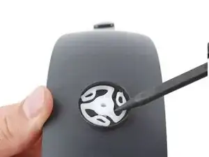
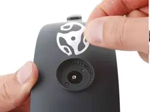
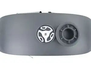
    • Insert an opening pick under the adjustment dial faceplate.

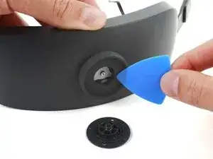
    • Pry up to separate the adhesive securing the faceplate.

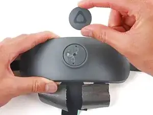
    • Remove the faceplate.

    • During reassembly, clean off any old adhesive using high-strength (>90%) isopropyl alcohol and a lint-free cloth. Use Tesa Tape to secure the faceplate to the adjustment dial.

  32. GYdIsObRFya21CUG
    GYdIsObRFya21CUG
    6GEF5CNfdCjWopwW
    • Use tweezers to remove the plastic tape covering the adjustment dial screw.

  33. iKx3LyXwNLxEgLBf
    iKx3LyXwNLxEgLBf
    1lNyinSSEHeHQSCZ
    • Use a Torx T5 screwdriver to remove the 3.8 mm-long screw securing the adjustment dial.

  34. pLDGbSGcKWBO6dbv
    pLDGbSGcKWBO6dbv
    DKXVLYUYG2JVXIUZ
    ldTi4ENcrNWiGNUD
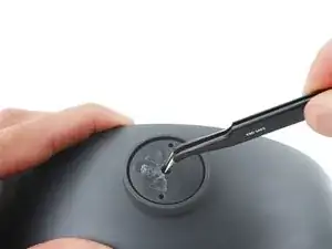
    • Insert an opening pick between the adjustment dial and the screw spacer.

    • Pry the screw spacer away from the adjustment dial to remove it.

  35. nbDeVKeCEsH6jhFR
    nbDeVKeCEsH6jhFR
    aFY2J5YYgrZAq2am
    • Pull the adjustment dial straight off the cradle and remove it.

  36. JoffxlfvHtFCKOZl
    JoffxlfvHtFCKOZl
    TBskuukYsw6nMiws
    nn6OuAfKP2plfCEP
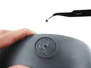
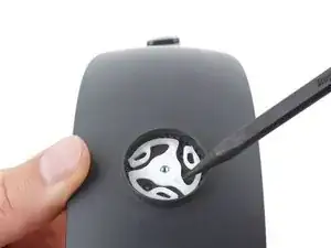
    • Use the point of a spudger to pry up the center of the sprocket.

    • Remove the adjustment dial sprocket.

  37. WodNm4fsRpbUNDfn
    WodNm4fsRpbUNDfn
    HuPGD3SrQIZ22SY2
    • Adjust the headstraps so they're fully retracted into the cradle.

    • Insert the sprocket so its teeth fully mesh with the teeth in the socket.

  38. pXctAnFEpa1xiJmy
    pXctAnFEpa1xiJmy
    2k3LwhPIDbSMNeaU
    dkBTDhcuAKbuhs2p
    • During reassembly, make sure three pegs on the adjustment dial are inserted into the three cutouts on the sprocket:

    • Three adjustment dial pegs

    • Three sprocket cutouts

    • Use the molding marks to align the dial over the cutouts on the sprocket.

    • You'll know the dial is installed correctly when it easily turns counterclockwise and clicks when turned clockwise.

  39. kW4SueDmtZlnRErY
    kW4SueDmtZlnRErY
    MFRSXUWmTN3xFAQK
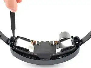
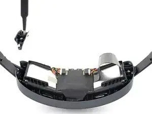
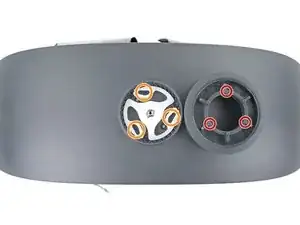
    • Use a T5 Torx screwdriver to remove the four 4.1 mm-long screws securing the headstrap guide.

  40. QaEB3CLRbvTqc24b
    QaEB3CLRbvTqc24b
    jFw4hescqMAFKTbM
    • Remove the headstrap guide

    • The headstraps will spring up when the guide is removed.

  41. K3J6omK6MbVNFE5D
    K3J6omK6MbVNFE5D
    3omyrfIEOiFaT5MN
    5YeD1P2mDQTkm45u
    • Remove the left and right headstraps

    • During reassembly, reinstall the right headstrap first and the left one on top of it.

Conclusione

Compare your new replacement part to the original part—you may need to transfer remaining components or remove adhesive backings from the new part before installing.

To reassemble your device, follow these instructions in reverse order.

Take your e-waste to an R2 or e-Stewards certified recycler.

Repair didn’t go as planned? Try some basic troubleshooting, or ask our Answers Community for help.

Chayton Ritter

Membro da: 21/08/20

17050 Reputazione

0 commenti