
Introduzione
This guide shows how to remove and replace a worn out battery in your Meta Quest 2 headset.
The battery is positioned above the screen and lens assembly and requires significant disassembly in order to reach it.
Note: You'll need a long PH00 bit or a dedicated PH00 screwdriver to remove some recessed screws.
-
-
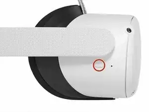
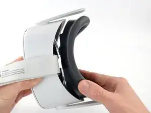
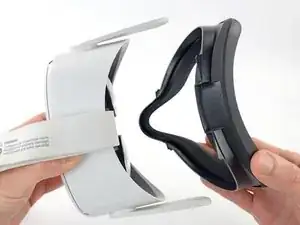
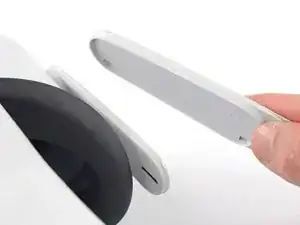
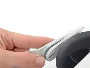
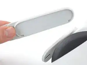
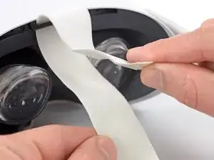
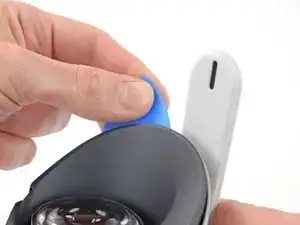
Use your fingers to grasp the right strap near the headset.
-
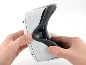
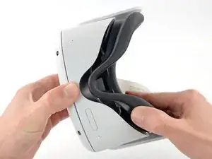
Peel the right strap away from the headset arm to unclip it.
-
-
-
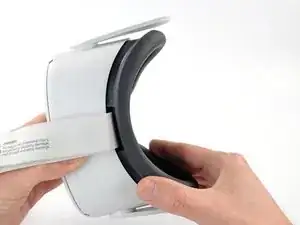
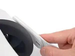
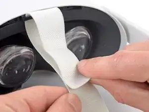
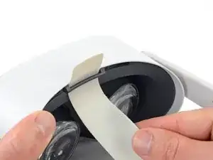
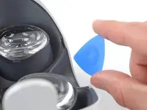
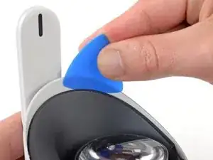
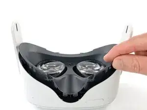
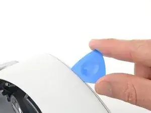
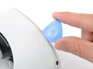
Insert an opening pick into the seam between the eyepiece trim and white outer shell, near the nose cutout.
-
-
-
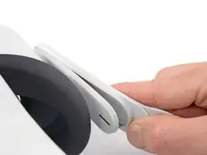
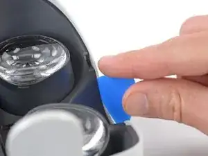
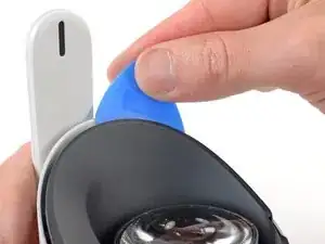
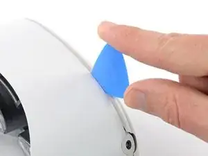
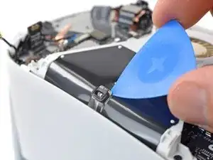
Slide the opening pick to the right along the seam to release the clips securing the eyepiece trim.
-
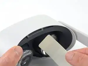
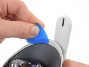
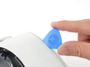
Pry with the opening pick to release the clips securing the right side of the eyepiece trim.
-
Leave the opening pick in the seam to prevent the clips from reengaging.
-
-
-
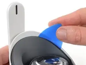
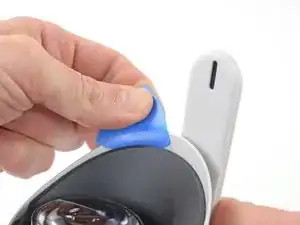
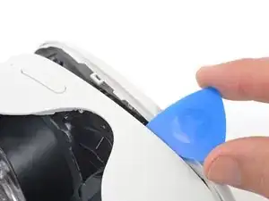
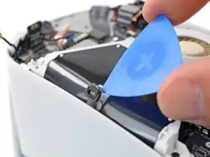
Repeat the prying procedure along the left edge to release the clips securing the eyepiece trim.
-
-
-
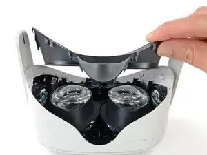
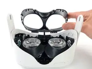
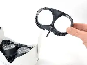
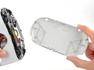
Lift the eyepiece trim slightly and tilt it towards the top edge of the headset.
-
Set the trim down on your work surface, making sure not to strain the cable.
-
-
-
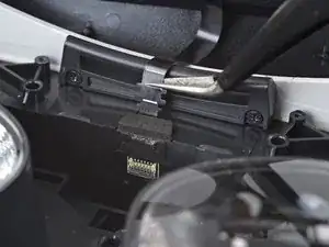
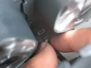
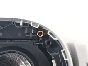
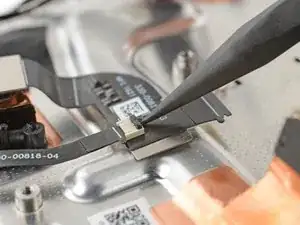
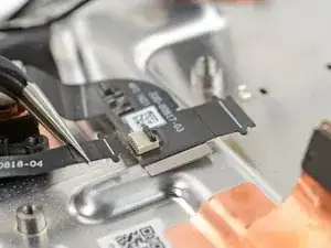
Use the point of a spudger to flip open the black lock tab on the ZIF connector securing the face sensor cable.
-
-
-
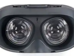
Make sure the lens spacing matches the spacing indicator. This allows the indicator peg to sit correctly in its notch.
-
If the lens spacing doesn't match the indicator, manually adjust the lens with your fingers.
-
-
-
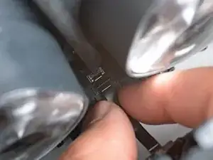
Thread your fingers through the eyepiece trim’s eyeholes and grasp the edges of the sensor cable.
-
Slide the sensor cable into the socket until the first set of tabs rests in the socket. This should flip the lock tab down partially.
-
Use a spudger to press the lock tab down towards the cable to lock it in place.
-
-
-
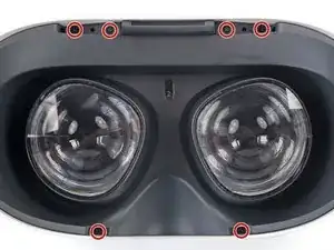
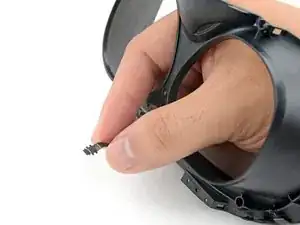
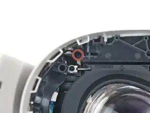
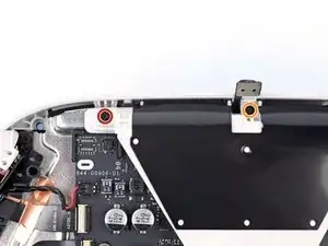
Use a Phillips screwdriver to remove the five 7.7 mm‑long screws securing the front cover to the headset:
-
One recessed in the top-left corner
-
One recessed in the top-right corner
-
Three along the lower edge
-
-
-
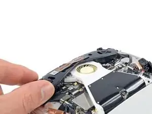
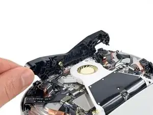
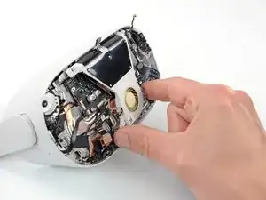
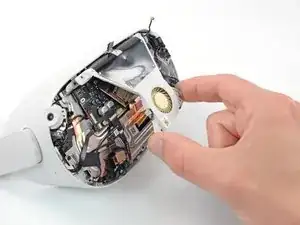
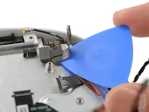
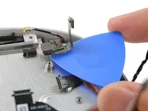
Insert an opening pick into the seam between the bottom edge of the front cover and the headset.
-
Pry with the opening pick to release the front cover clips.
-
-
-
Slide the opening clip along the seam and pry to release all the clips securing the front cover.
-
-
-
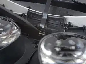
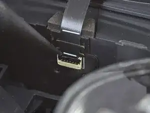
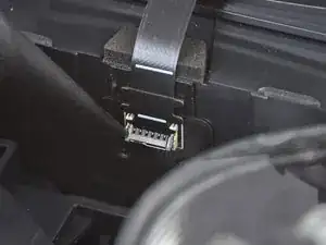
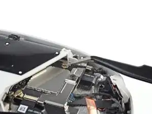
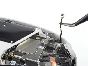
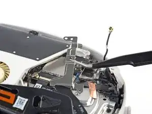
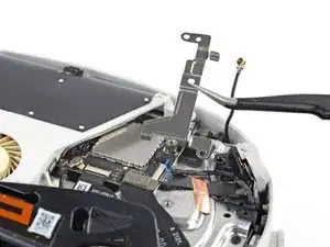
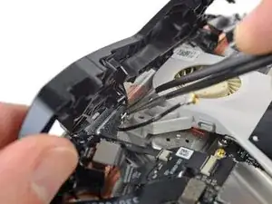
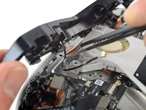
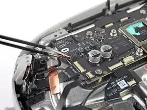
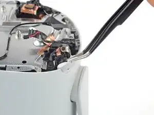
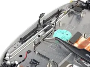
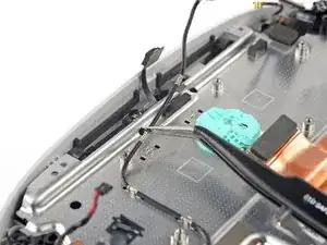
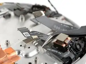
Use a pair of tweezers to grasp the metal neck of the top-right antenna cable.
-
Lift the antenna connector straight up to disconnect it.
-
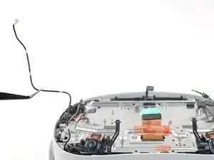
Guide the antenna cable out of its metal clip holding it in place.
-
-
-
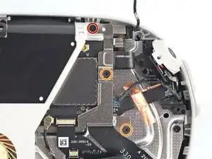
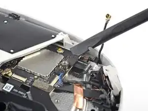
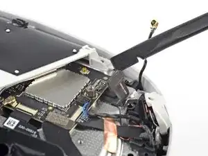
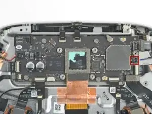
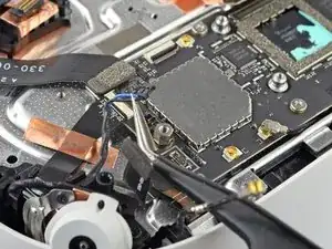
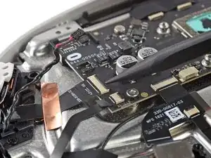
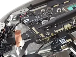
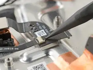
Use a Phillips screwdriver to remove the three screws securing the battery cable bracket:
-
One 4.4 mm‑long screw
-
Two 2.3 mm‑long screws
-
-
-
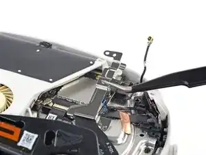
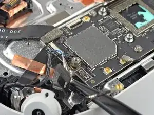
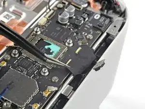
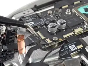
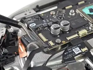
Use tweezers or your fingers to grasp the battery cable bracket.
-
Twist the cable bracket slightly so that its bottom left corner unclips from the motherboard.
-
Remove the battery cable bracket.
-
-
-
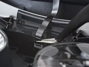
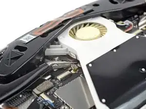
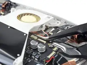
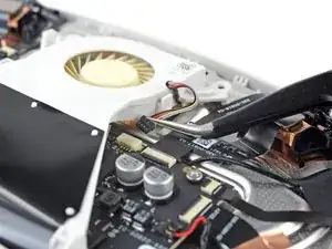
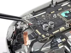
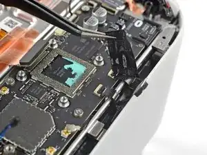
Insert one arm of a pair of tweezers under the metal neck of the black antenna cable near the fan assembly.
-
Lift the antenna connector straight up to disconnect it.
-
Guide the antenna cable out of its metal clip holding it in place.
-
-
-
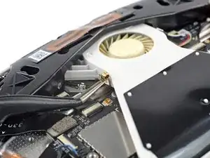
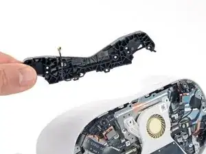
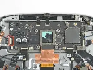
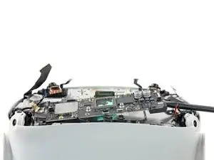
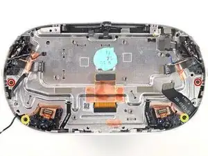
Use a Phillips screwdriver to remove the eight screws securing the antenna assembly to the headset:
-
Four 4.4 mm‑long screws
-
Two 4.8 mm‑long screws
-
Two 10.7 mm‑long screws
-
-
-
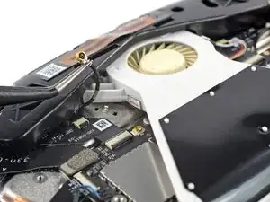
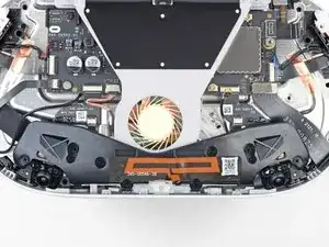
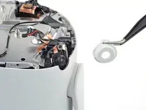
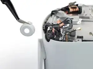
Use the point of an opening pick to loosen the adhesive securing the LED flex cable from the top of the fan assembly.
-
-
-
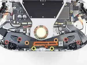
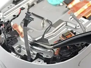
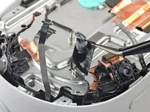
Remove the two screws securing the fan assembly to the headset:
-
One 4.4 mm‑long Phillips screw
-
One 3.6 mm‑long Torx T2 screw
-
-
-
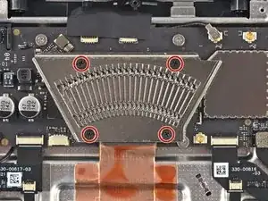
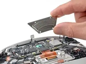
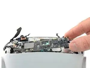
Use a Phillips screwdriver to remove the four 2.3 mm‑long screws securing the heat sink to the motherboard.
-
-
-
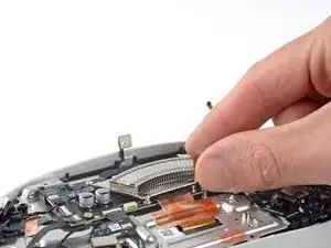
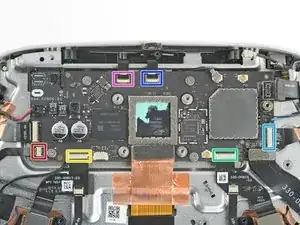
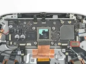
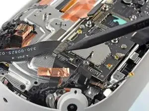
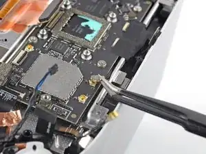
Use tweezers to grip the left speaker cables at the base of their motherboard connector.
-
Lift the connector gently straight up to disconnect it.
-
-
-
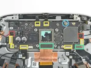
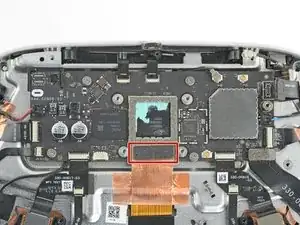
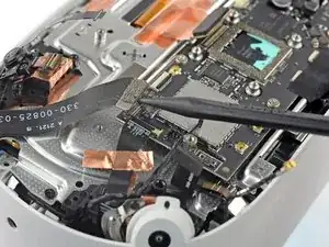
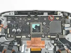
Use a clean fingernail or a spudger to pry up the lock tab securing the top left camera cable.
-
-
-
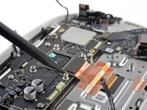
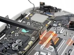
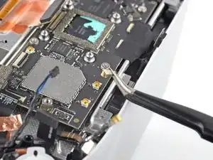
Move counter-clockwise around the motherboard and disconnect the remaining six ZIF connectors:
-
Power button and LED board
-
Bottom left camera
-
Bottom right camera
-
Top right camera
-
Face sensor interconnect cable
-
Indicator LED cable
-
-
-
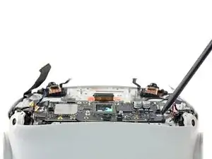
Insert one arm of a pair of tweezers under the metal neck of the side antenna cable.
-
Lift the antenna connector straight up to disconnect it.
-
-
-
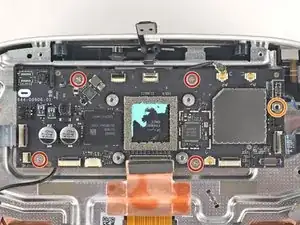
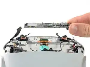
Remove the five screws securing the motherboard to the headset:
-
Four 3.8 mm‑long Phillips screws
-
One 6 mm‑long 3.5 mm hex standoff screw
-
-
-
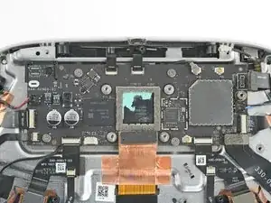
Use your fingers or tweezers to peel and remove the two camera covers from the top cameras.
-
-
-
Use a spudger to pry up the black lock tab securing the left microphone flex cable to the left interconnect cable.
-
Use your fingers or tweezers to slide the microphone cable out of the ZIF connector.
-
-
-
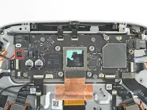
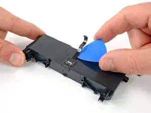
Slide the point of an opening pick underneath the battery flex cable to loosen the adhesive securing it from the headset.
-
-
-
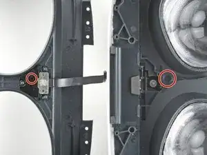
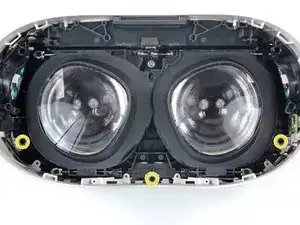
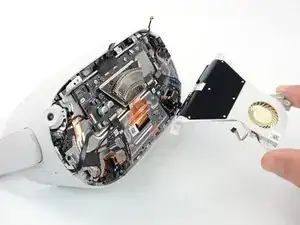
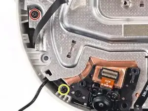
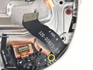
Use a Phillips screwdriver to remove the four screws securing the screen and lens assembly to the frame:
-
Two 6.5 mm‑long screws
-
Two 7.7 mm‑long screws
-
-
-
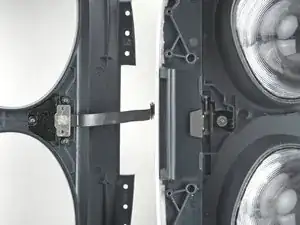
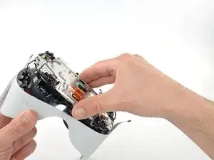
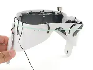
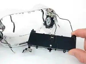
Grasp the screen and lens assembly with your fingers.
-
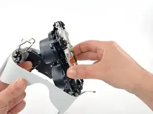
Slowly lift and separate the assembly from the outer shell, taking care to reposition any cables that get in the way.
-
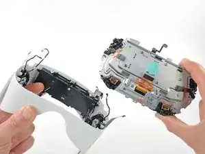
Remove the screen and lens assembly.
-
-
-
Three cables along the top edge—two flex cables and one LED flex cable
-
Two cables in the top right corner—the battery connector and an antenna cable
-
Two cables along the right edge—an antenna cable and a wide flex cable
-
Two flex cables along the bottom edge
-
Three cables along the left edge—one antenna cable, one flex cable, and one speaker cable
-
-
-
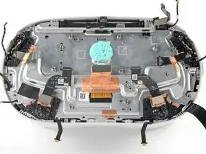
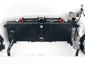
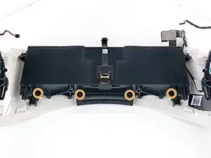
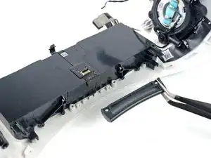
Use a Phillips screwdriver to remove the six 4.5 mm‑long screws securing the battery to the outer shell:
-
Two along the front edge
-
Four along the back edge
-
-
-
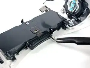
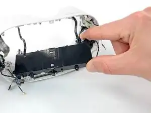
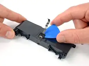
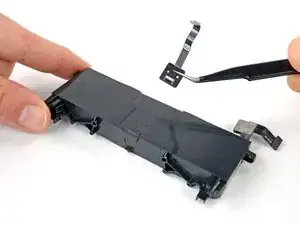
Slide an opening pick under the face sensor interconnect cable to loosen the adhesive securing it to the battery.
-
Remove the sensor interconnect cable.
-


To reassemble your device, follow these instructions in reverse order.
For optimal performance, after completing this guide, calibrate your newly installed battery.
Take your e-waste to an R2 or e-Stewards certified recycler.
Repair didn’t go as planned? Try some basic troubleshooting, or ask our Answers community for help.

Un commento
Life is too short.