Introduzione

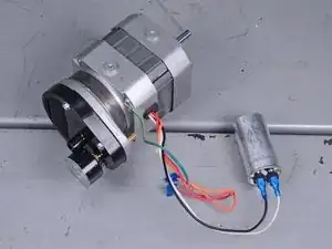
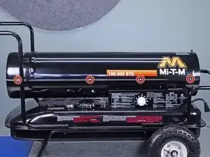
Follow this guide to replace the motor and pump assembly on a Mi-T-M heater model MH-0190-0M10.

This guide includes the motor, pump, and capacitor all as one assembly. If only the capacitor needs to be replaced, follow this guide.

After the new motor and pump assembly is installed, use a flat blade screwdriver to adjust the pump pressure back to 7.5 PSI as instructed on page 17 of the user manual.

  1. YRbIqSAM36IanG1s
    YRbIqSAM36IanG1s
    YiwWQ4jHxTGCAfbx
    • Power off the machine at least one hour prior to starting repairs. Ensure the machine is completely cool to the touch.

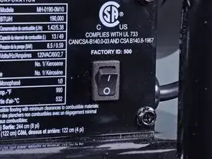
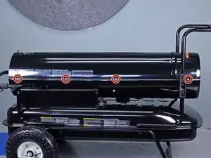
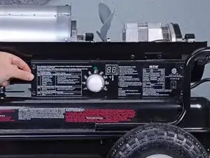
    • Flip the power switch into the OFF position.

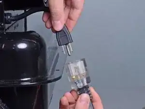
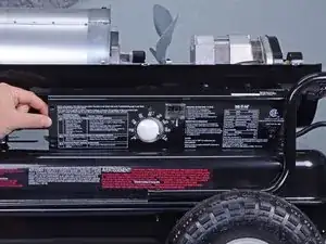
    • Unplug any extension cords from the included power cord.

  2. BCnDXObnU4aLlUnw
    BCnDXObnU4aLlUnw
    FLPeVeegkam51uFt
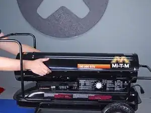
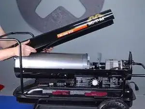
    • Use a 5/16 inch socket or Phillips screwdriver to remove the eight screws securing the upper shell, four on each side.

  3. g3goHXdvbgJkfYnr
    g3goHXdvbgJkfYnr
    kk5TiRy4kNpsgEAK
    • Lift the upper shell straight up off of the machine to remove it.

  4. QgXOps5UNWMx26Kw
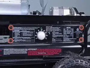
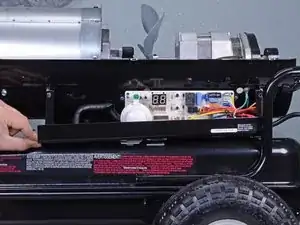
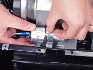
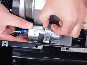
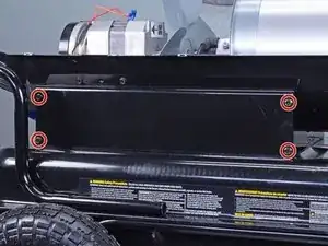
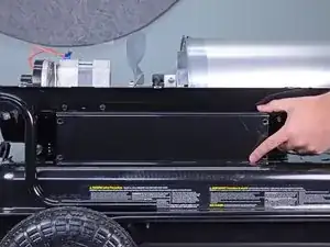
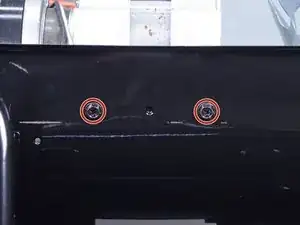
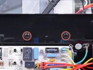
    • Use a 5/16 inch socket or Phillips screwdriver to remove the four bolts securing the right-side cover.

  5. uqNbUREyKHZtrCZZ
    uqNbUREyKHZtrCZZ
    At6qgsDHeHEERmKO
    eBoB3rmIPhOQgVco
    • Tilt the right-side cover down to access the PCB board.

    • Do not fully remove the right-side cover, it is still attached via the on/off switch.

    • During reassembly, ensure the display window is aligned with the LCD display before you press the cover into place.

  6. dQqwMw1xAdemtLct
    dQqwMw1xAdemtLct
    MlXd6KO1SdtlEVpa
    EI3O1ZuBfSuFHOOL
    • There are two wires connecting the power switch to the main PCB assembly.

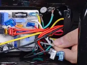
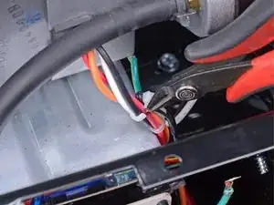
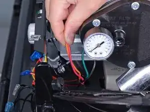
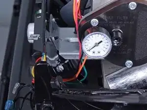
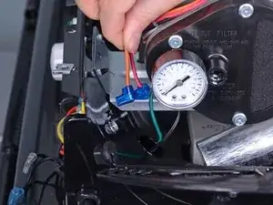
    • Use needle nose pliers to remove the wire with the blue connector.

    • Remove the wire with the clear connector.

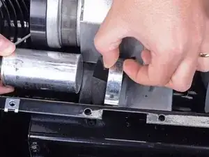
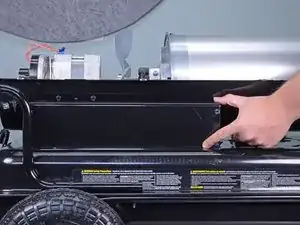
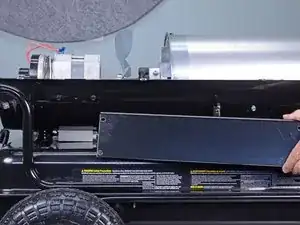
    • Remove the right-side cover.

    • During reassembly, install the power switch wires back in their original locations with the blue wire above the clear wire.

  7. kk1dGrTKwNIkneK1
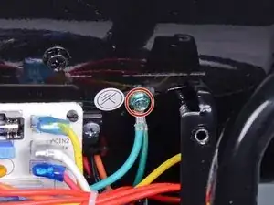
    • Use a 5/16 inch socket or Phillips screwdriver to remove the screw securing the two green ground wires to the frame.

  8. SRoyUAOKbPcPnFk3
    SRoyUAOKbPcPnFk3
    rWDYyBHJ2o3iXCfN
    XsWrjTWThK6qGvKN
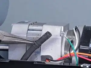
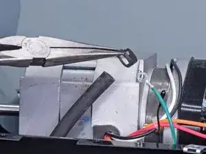
    • Use a pair of needle nose pliers to release the hose clamp from the fuel line.

    • Slide the hose clamp off of the nipple, about one inch down the fuel line.

  9. KvLNyJ6PsSVZI4BY
    KvLNyJ6PsSVZI4BY
    HWSKZCbtai1bLM6Y
    • Pull to disconnect the fuel line from the motor and pump assembly.

  10. IjYsZVdhslMuAdKa
    IjYsZVdhslMuAdKa
    j4Ojr6UsBLHHZ1Sy
    • Use a pair of needle nose pliers to remove the fuel line hose clamp.

  11. kSF5sD6SlpZtjDyu
    kSF5sD6SlpZtjDyu
    mJPBor3cZwwRxt6a
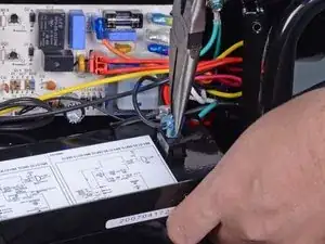
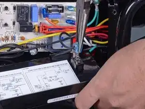
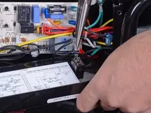
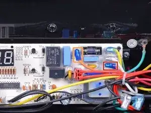
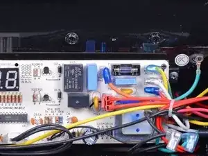
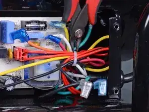
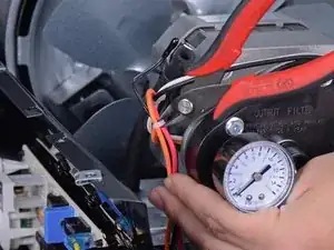
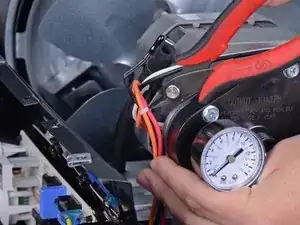
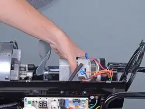
    • Use a pair of needle nose pliers to disconnect the wires connecting the motor and pump assembly to the main PCB board:

    • One red cable labeled MOTOR 2 on the main PCB board

    • One orange cable labeled MOTOR 1 on the main PCB board

    • Pull the wires with the needle nose pliers by their connectors and not the wires themselves.

  12. JXMMkP2GAZZYmnQP
    JXMMkP2GAZZYmnQP
    C2D6HtQ5CTRQhiMF
    IR5nJPhw1AEocvIE
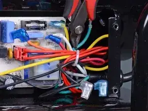
    • Use a pair of flush cutters to cut the cable tie harnessing the wires running from the main PCB assembly.

    • Remove the cable tie.

    • During reassembly, install a new cable tie.

  13. JkQjgpcUJ1pKCYCY
    JkQjgpcUJ1pKCYCY
    y4OCqbT6GkWlsBuH
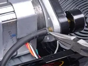
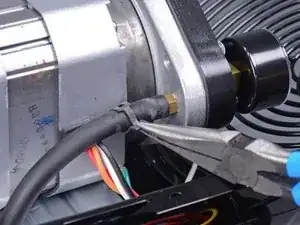
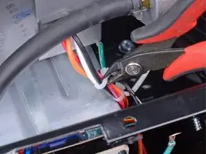
    • Use a pair of flush cutters to cut the cable tie harnessing the orange, red, white, and black wires near the fuel line.

    • During reassembly, install a new cable tie.

  14. in3RPCmF2Qofavgq
    in3RPCmF2Qofavgq
    Rem6AlLZZwFwJTYS
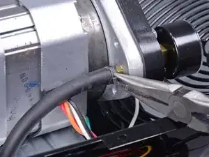
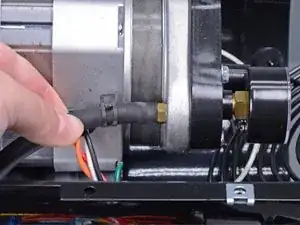
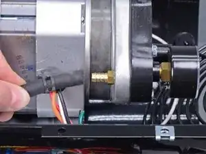
    • Use a pair of flush cutters to cut the cable tie harnessing the orange and red wires next to the motor.

    • During reassembly, install a new cable tie.

  15. lyCNIKFIc6nLQrlf
    • Use a Phillips screwdriver to remove the screw securing the capacitor band clamp.

  16. 1UjMBtJCdwnQDMIe
    1UjMBtJCdwnQDMIe
    BTmvJ2dV3OpPFhF5
    jdJEFFVOUjbxZr5t
    • Remove the capacitor from the band clamp.

    • During reassembly, realign the foam padding between the capacitor and the band clamp.

  17. eO2HWOPGoXVoHVTo
    eO2HWOPGoXVoHVTo
    xtCmVOuQRrwkT2Zv
    oUuLKRQfLyWNiUJD
    • Feed the orange and red wires out through the opening in the lower shell.

  18. TOsmmDaEVW5lKBNW
    • Use a 5/16 inch socket or Phillips screwdriver to remove the four bolts securing the left-side cover.

  19. 5kNedFTAdMLwUKxF
    5kNedFTAdMLwUKxF
    lZgc2I6ZF2SXLV4X
    pvKpxcEe5WMfKymW
    • Remove the left-side cover.

  20. IeWAKogRPFmMEiIE
    IeWAKogRPFmMEiIE
    FHaRJSPRFbAmvAE3
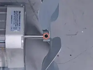
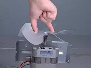
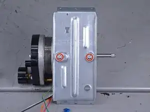
    • Use a 5/16 inch socket or Phillips screwdriver to remove the four screws securing the motor mount bracket, two on each side.

  21. PhfXTW2rBsWs1uGu
    PhfXTW2rBsWs1uGu
    BTqHYjCajSJ2iPUF
    • Lift the motor, pump, and bracket assembly straight up out of the machine.

  22. jB5WfHCGPKxBEIua
    • Use a 3 mm hex key to loosen the set screw securing the fan to the motor shaft.

    • The set screw does not need to be fully removed.

  23. JdJeuP6iJT1p4DLA
    JdJeuP6iJT1p4DLA
    XhENeCh1YEkPyYMa
    • Remove the fan.

  24. TomOwmYoNVUSy3wf
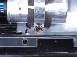
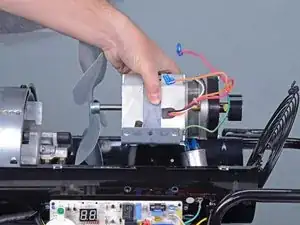
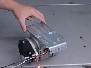
    • Use a 5/16 inch socket or Phillips screwdriver to remove the two screws securing the motor and pump assembly to the motor mount bracket.

  25. uDfPsxVHldX5eplP
    uDfPsxVHldX5eplP
    KHeIBPSg5XSbvGj4
    x5xPyYHer2GNZDqJ
    • Remove the motor mount bracket.

    • Only the motor and pump assembly remain.

Conclusione

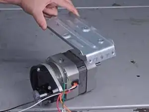
To reassemble your device, follow these instructions in reverse order.

Sam Omiotek

Membro da: 25/02/19

71915 Reputazione

0 commenti