Introduzione
Follow this guide to remove or replace the motherboard in a Motorola Moto E6 Plus.
Before you begin, download the Rescue and Smart Assistant app to backup your device and diagnose whether your problem is software or hardware related.
-
-
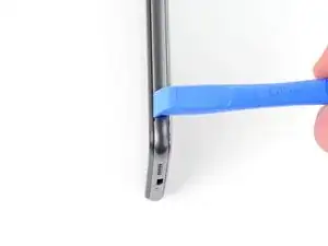
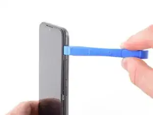
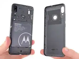
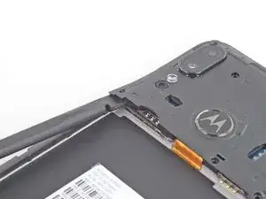
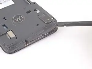
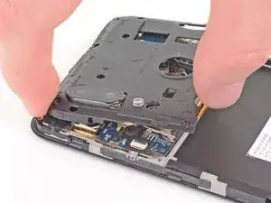
Use an opening tool or your fingernail to pry the back cover away from the frame using the notch at the bottom right corner.
-
-
-
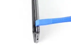
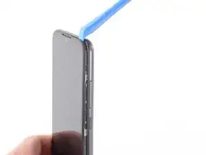
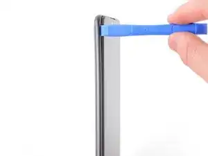
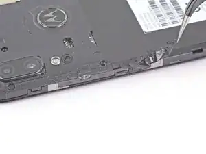
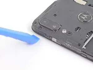
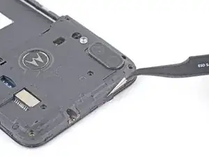
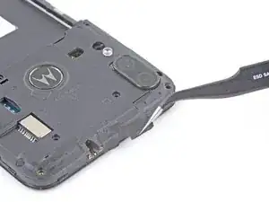
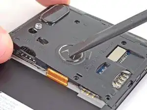
Use an opening tool or your fingernail to release the clips on the right edge by sliding up and around the top right corner.
-
-
-
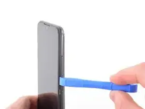
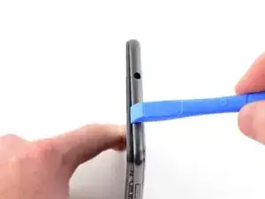
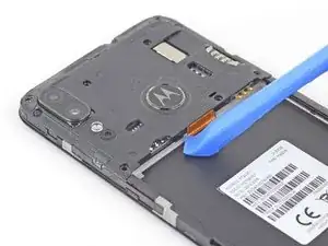
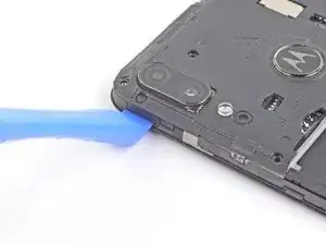
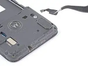
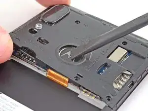
Continue to slide the opening tool or your fingernail across the top edge to release the clips securing the back cover to the frame.
-
-
-
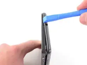
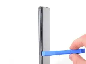
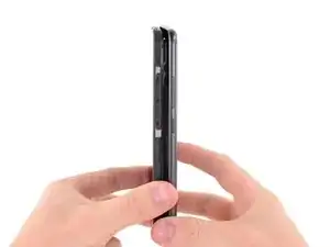
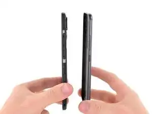
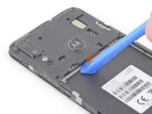
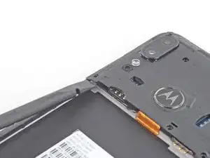
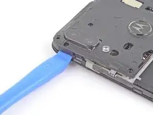
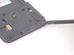
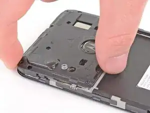
Continue to slide the opening tool or your fingernail down the left edge to release the clips.
-
-
-
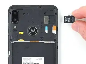
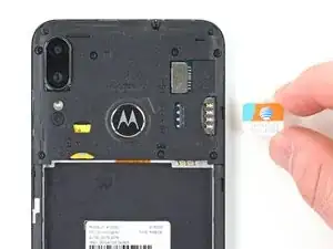
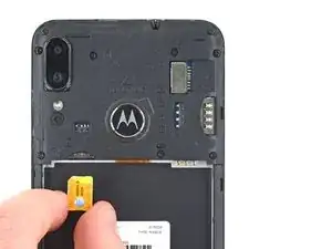
Use a spudger or your fingernail to remove the Micro SD card, the Micro SIM card, and the Nano SIM card.
-
-
-
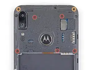
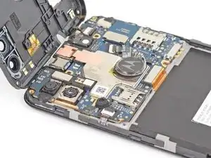
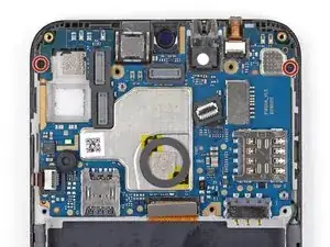
Use a Torx T3 driver to remove the five 3.6 mm-long screws securing the motherboard cover to the frame.
-
Use a Phillips screwdriver to remove the two 3.1 mm-long screws.
-
-
-
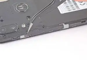
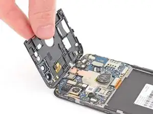
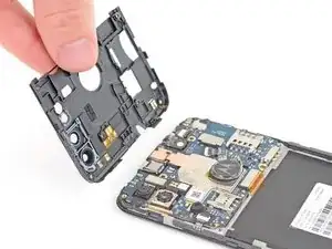
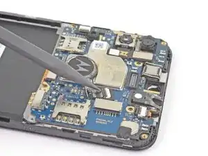
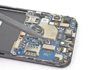
Use your fingers to twist the motherboard cover counterclockwise to release the clips securing the motherboard cover.
-
-
-
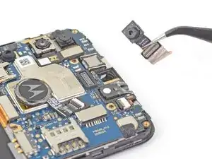
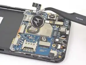
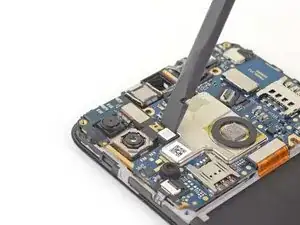
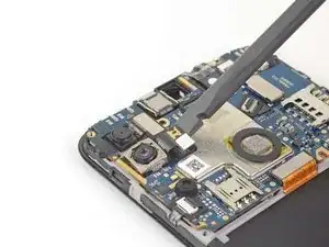
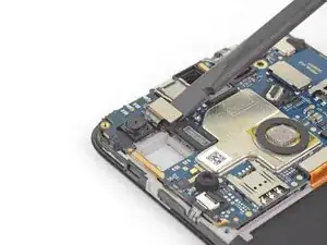
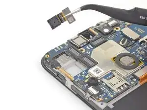
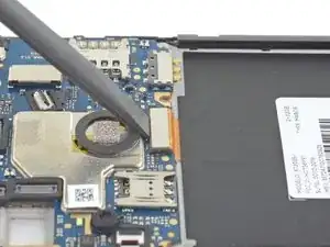
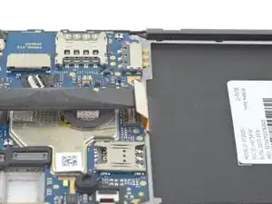
Use the flat end of a spudger to lift the front camera's press connector straight up to disconnect it from the motherboard.
-
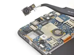
Remove the front camera.
-
-
-
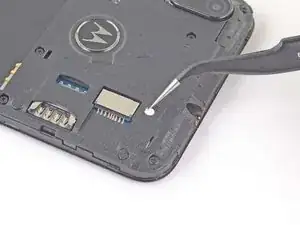
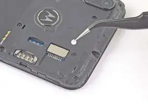
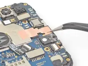
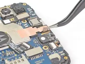
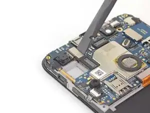
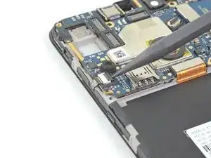
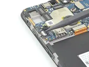
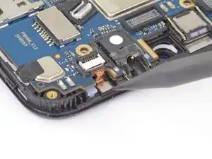
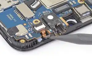
Use the tip of a spudger, an opening tool, or your fingernail to flip up the small, hinged locking flap on the fingerprint sensor ZIF connector.
-
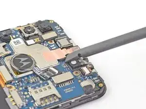
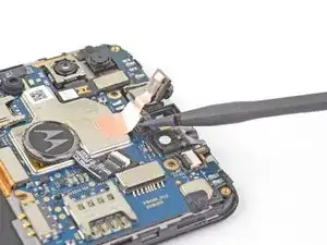
Pull the fingerprint sensor ribbon cable straight out of the connector to remove it.
-
Remove the fingerprint sensor.
-
-
-
Use the flat end of a spudger to disconnect the rear camera from the motherboard by lifting straight up on the press connector.
-
Remove the rear camera.
-
-
-
Use the flat end of a spudger to disconnect the depth information camera from the motherboard by lifting straight up on the press connector.
-
Remove the depth information camera.
-
-
-
Use the tip of a spudger, an opening tool, or your fingernail to flip up the small, hinged locking flap on the button ZIF connector.
-
Use a pair of tweezers to pull the button ribbon cable straight out of the connector.
-
-
-
Use the flat end of a spudger to disconnect the motherboard flex cable by lifting straight up on the press connector.
-
-
-
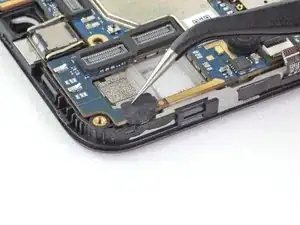
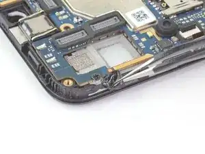
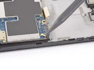
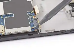
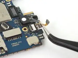
Use the pointed end of a spudger to pry the IR sensor out of the frame.
-
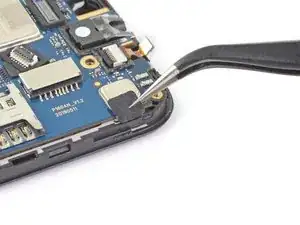
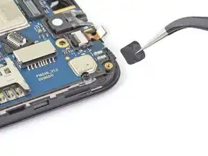
Remove the IR sensor gasket from the frame.
-
-
-
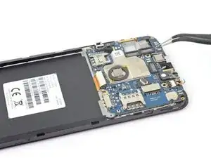
Use a Phillips screwdriver to remove the two 3.1 mm-long screws securing the motherboard to the frame.
-
-
-
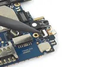
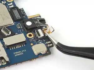
Use the pointed end of a spudger to disconnect the coaxial cable by prying up on the cable as close to the connector as possible.
-
-
-
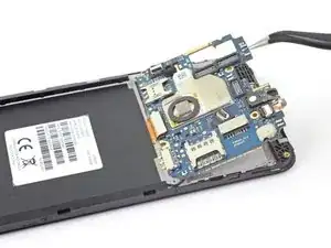
Use the tip of a spudger, an opening tool, or your fingernail to flip up the small, hinged locking flap on the IR sensor ZIF connector.
-
-
-
Use a pair of tweezers to pull the IR sensor ribbon cable straight out of the connector.
-
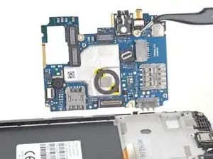
Only the motherboard remains.
-


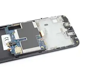


To reassemble your device, follow these instructions in reverse order.
Take your e-waste to an R2 or e-Stewards certified recycler.
Repair didn’t go as planned? Try some basic troubleshooting, or ask our Motorola Moto E6 Plus Answers community for help.