Introduzione
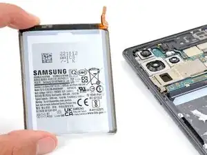
Follow this guide to replace the battery in your Samsung Galaxy S22 Ultra.
This guide is for the battery itself. If you're replacing the OEM screen and battery assembly (the frame, screen, and battery as one piece), follow this guide.
You'll see references to the Samsung Self Repair Kit throughout this guide. Ignore those bullets, as they don't apply to this guide.
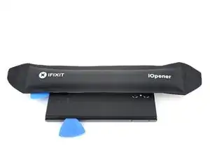
-
-
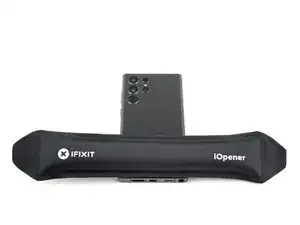
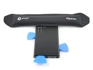
While you wait for the adhesive to soften, note the following:
-
There's adhesive securing the back cover around the perimeter of the frame.
-
-
-
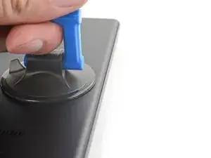
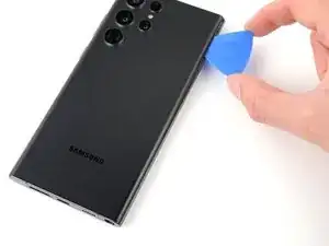
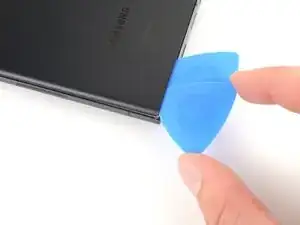
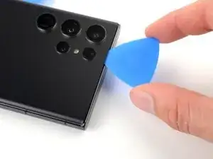
Apply a suction handle to the back cover, as close to the center of the right edge as possible.
-
Pull up on the suction handle with strong, steady force to create a gap between the cover and the frame.
-
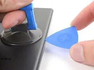
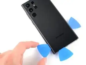
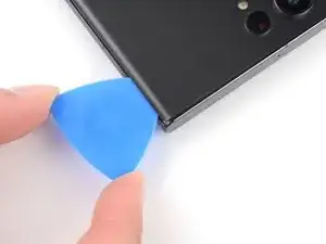
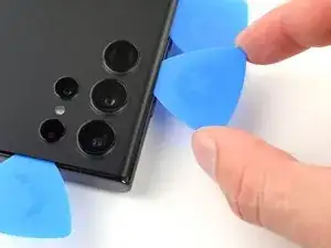
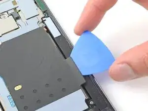
Insert an opening pick into the gap.
-
-
-
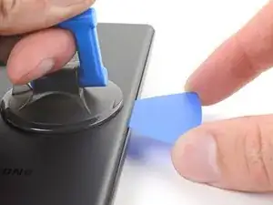
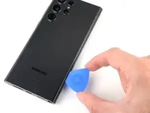
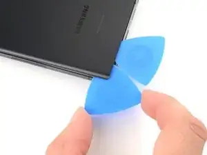
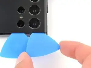
Slide the pick back and forth along the right edge to slice through the adhesive.
-
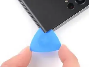
Leave the pick inserted near the bottom of the right edge to prevent the adhesive from resealing.
-
-
-
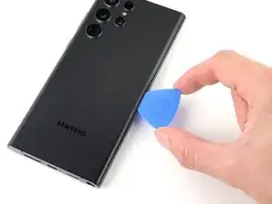
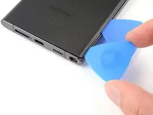
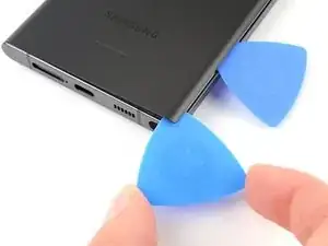
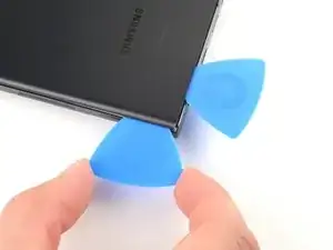
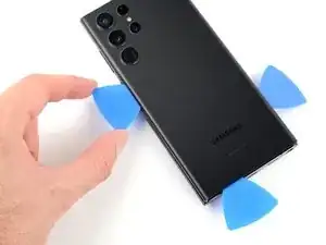
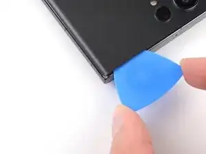
Insert a second opening pick at the bottom right corner.
-
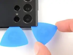
Angle the pick upward to match the curved edge and rotate it around the bottom right corner.
-
-
-
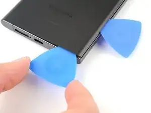
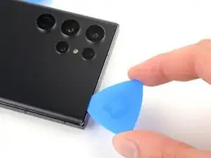
Slide your opening pick to the bottom left corner to slice the adhesive.
-
Leave the pick in the bottom left corner to prevent the adhesive from resealing.
-
-
-
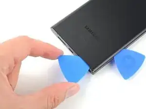
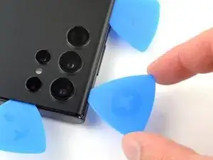
Insert a third opening pick at the bottom left corner.
-
Angle the pick upward to match the curved edge and rotate it around the bottom left corner.
-
-
-
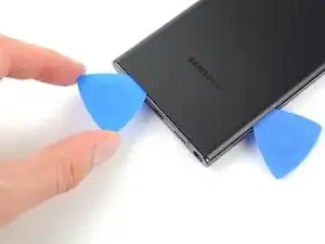
Slide your opening pick along the left edge to slice the adhesive, stopping when you reach the power button.
-
Leave the pick in the left edge to prevent the adhesive from resealing.
-
-
-
Insert an opening pick in the gap at the top right edge.
-
Angle the pick upward to match the curved edge and rotate it around the top right corner.
-
-
-
Slide the pick to the top left corner to slice the adhesive.
-
Leave the pick in to prevent the adhesive from resealing.
-
-
-
Insert an opening pick in the gap at the top left edge.
-
Angle the pick upward to match the curved edge and rotate it around the top left corner.
-
-
-
Slide the pick toward the bottom camera to slice through the remaining adhesive, stopping before you reach the power button.
-
-
-
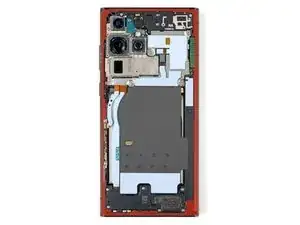
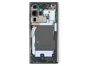
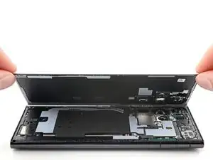
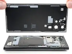
Grab and remove the back cover.
-
This is a good point to power on your phone and test all functions before sealing it up. Be sure to power your phone back down completely before you continue working.
-
Remove any adhesive chunks with a pair of tweezers or your fingers. Apply heat if you're having trouble separating the adhesive.
-
If you're using Samsung custom-cut adhesives, follow this guide.
-
If you're using double-sided tape, follow this guide.
-
-
-
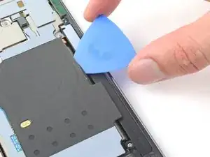
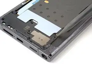
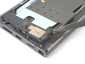
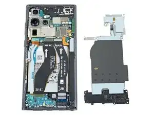
Insert an opening pick between the right edge of the wireless charging coil and the battery.
-
Slide the pick along the right edge to separate the adhesive.
-
-
-
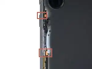
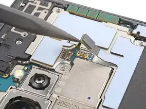
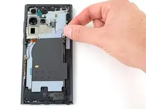
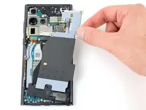
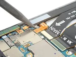
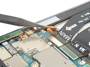
Use the pointed end of a spudger to pry and disconnect the NFC antenna press connector from the motherboard.
-
Repeat for the wireless charging coil press connector.
-
-
-
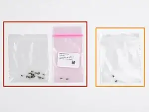
Label the bag with the most screws and the colored bag #3428.
-
If you're replacing the screen and battery, label the clear bag with two screws #3439.
-
-
-
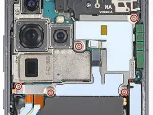
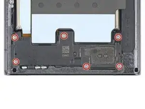
Use your Phillips screwdriver to remove the five 3.5 mm-long screws securing the NFC antenna and charging coil.
-
-
-
Insert the pointed end of your spudger between the upper right corner of the loudspeaker and the frame.
-
Pry up to unclip the loudspeaker from the frame.
-
-
-
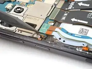
Use the pointed end of your spudger to pry up and disconnect the lower 5G mmWave antenna press connector.
-
-
-
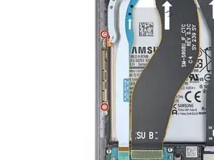
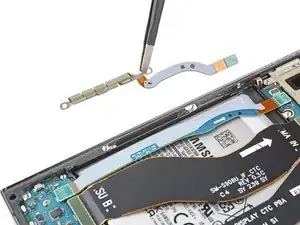
Use your Phillips screwdriver to remove the two 3.5 mm-long screws securing the antenna bracket.
-
-
-
Insert the pointed end of your spudger between the lower screw mount of the antenna bracket and the frame.
-
Pry up on the bracket until you can grab it with blunt nose tweezers or your fingers.
-
Remove the lower 5G mmWave antenna.
-
-
-
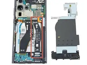
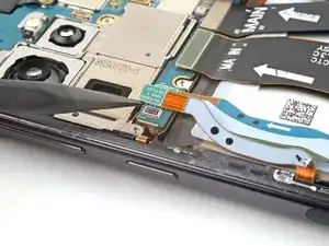
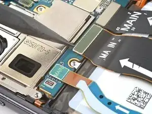
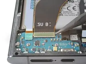
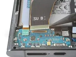
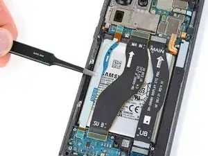
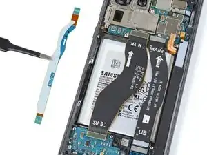
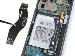
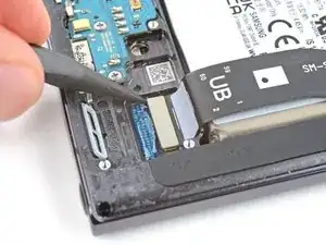
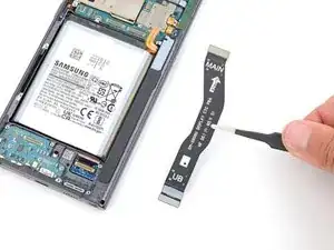
Use the pointed end of your spudger to pry up and disconnect the primary interconnect cable from the motherboard.
-
Repeat for the secondary interconnect located to the left of the primary cable.
-
-
-
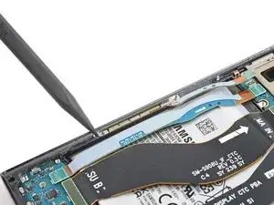
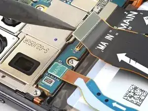
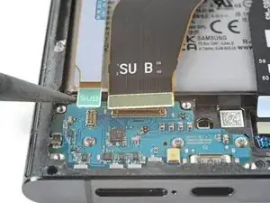
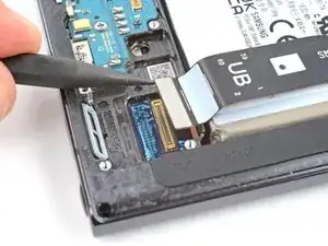
Use the pointed end of your spudger to pry up and disconnect the primary interconnect cable from the charging board.
-
Repeat for the secondary interconnect cable.
-
-
-
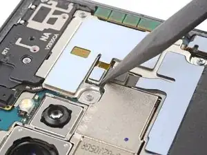
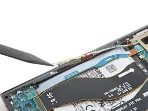
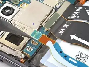
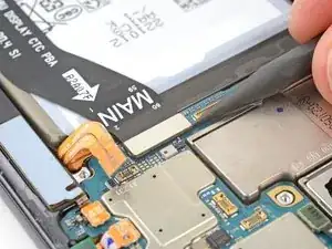
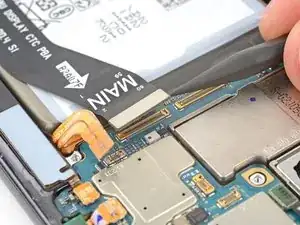
Use the pointed end of your spudger to pry up and disconnect the screen press connector from the motherboard.
-
-
-
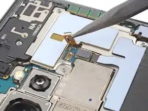
Use the pointed end of your spudger to pry up and disconnect the screen press connector from the bottom right corner of the phone.
-
-
-
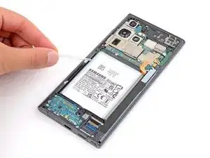
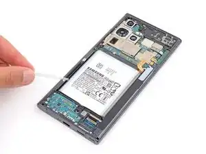
Use a pipette or syringe to apply a few drops of highly-concentrated isopropyl alcohol (greater than 90%) between the left edge of the battery and frame.
-
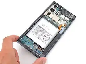
Elevate the left edge of the phone for one minute to allow the isopropyl alcohol to flow under the battery and soften the adhesive.
-
-
-
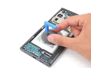
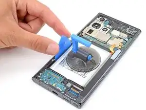
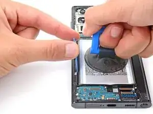
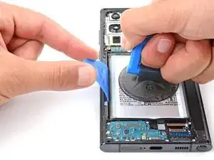
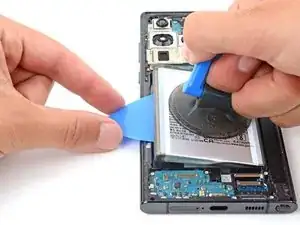
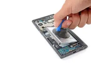
Apply a suction cup to the battery, as close to the center of the left edge as possible.
-
Insert the tip of an opening pick between the left edge of the battery and frame.
-
Push the opening pick down and rotate it so the long end is between the battery and frame.
-
-
-
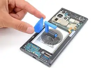
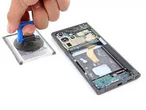
Pull up on the suction cup with strong, steady force while prying the battery up with the opening pick.
-
Maintain constant pressure on the pick and suction cup until the battery separates from the frame.
-

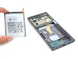
To reassemble your device, follow these instructions in reverse order.
For optimal performance, calibrate your newly installed battery after completing this guide.
Take your e-waste to an R2 or e-Stewards certified recycler.
Repair didn’t go as planned? Try some basic troubleshooting, or ask our Answers community for help.

I try to find the correct celsius value to heat the bag or direct temp to the sides of the phone. A reference should be a good thing to have. I have a heat bed I use to heat it up. I think 80c can work
Tobias Müllauer -