Introduzione

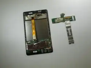
Questa guida illustra la rimozione della scheda figlia. La scheda figlia contiene la porta micro USB.

  1. xHPWImtKyPYRU6Qm
    xHPWImtKyPYRU6Qm
    EZf335HVLEPfcfkW
    • Spegni il telefono.

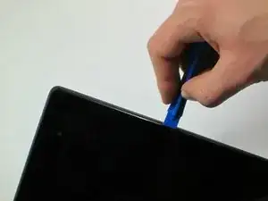
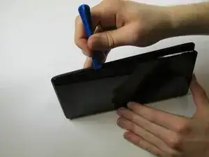
    • Incunea il tuo strumento di apertura in plastica nella giunzione tra le due facce del dispositivo. Fai leva e apri un lato alla volta.

    • Non far leva vicino alla porta USB alla base del dispositivo, perché potresti rompere il pannello posteriore.

    I had a heck of a time doing this, spent ten or twenty minutes carefully prying, and I STILL cracked the case. At least on mine, the case was held in VERY well and required prying pretty much everywhere before it would let go. The tools I bought from iFixit really helped, but still a royal pain to open.

    pacmanmaster -

    a couple of obscure things that might help in opening:

    guitar pick. get a few; they are cheap.

    a prying device made for the sign industry: its called"lil' chizler". I have found that this to be the most helpful opening tool.

    http://www.ebay.com/itm/like/16184595677...

    also

    https://www.qualitylogoproducts.com/trad...

    you can use the broken screen unit to test.

    Len Gorsky -

    Add "remove the sim tray"...

    Iain Lennon -

    I echo the previous - a right royal pain to get the cover off! I started on the right side as seemed to be more give there… iFixit tools helped tho!

    Steven Emery -

    Just for the sake of clarity, I would add that you need to pry between the plastic bezel and the back casing. Not between the glass and bezel. Someone had already tried on the one I worked on and part of the bezel was missing in the top right corner. Made my job easier!

    The best tools for this part are definitely something like the iFixit Jimmy and their opening tool, a few guitar picks and a spudger. Not too difficult once you get the first separation.

    Cool_Breeze -

    I managed to easily crack the screen, guess I’ll have to order a new one and “try” to put it in, in addition to the original job of replacing a dead battery on Nexus 7 2013..ahhhhhh, slow learner…

    Gary Stamey -

    Opened the case for the first time. It took me a while to find any gaps, but I found that the easy way to begin was using your fingernail to get into the sides. The middle left and middle right seemed a lot easier to…slip a nail in compared to the rest of the case, especially the corners and the top and bottom. With a small opening on both sides I used the opening tool to increase the gaps while using a couple of guitar picks to prop up the device against the back case. With most of the sides exposed, I worked on the bottom (create opening, leave a guitar pick to keep that part open, use the opening tool to get the rest out), and the opening was pretty much complete.

    So far only the corners of the back case showed small cracks and my screen was pretty much unscathed.

    Nam Lam -

    This method worked best for me! Start opening on the middle left and right sides, then prop them open with guitar picks and use to the opening tool (carefully) prying up several times moving away from the middle towards the corners to pop off the back casing.

    Frank's VR -

  2. RcOxAHLDxh4N6FCW
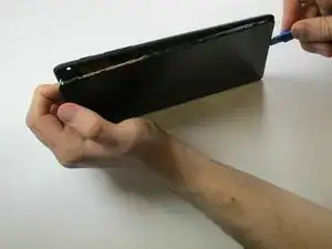
    • Usa anche le dita attorno alla giunzione tra il dispositivo e la cover posteriore. Usa il tuo strumento di apertura in plastica o le dita per separare ciascun lato fino a staccare completamente tra loro il dispositivo e la cover posteriore.

    • Fai attenzione quando lavori vicino agli angoli, la scocca del dispositivo può rivelarsi fragile.

    I did two of these. The first was a WIFI model that the earphone plug had become intermittant (just needed to resolder the connections.) The second an LTE version that the battery had gone bad and swelled to about 3 times the size.

    The swollen battery had pushed the glass free of the upper mount, and made the entire thing extremely tight.

    The WIFI one came apart easily like described.

    The LTE one (with the swollen battery) required a lot more care and a lot more force/damage to get into the gap between the two plastic pieces. (I did the wifi one first, so I could easily tell the difference.

    So depending on your situation...it may not be easy to separate the pieces...but remmber, the thin glass is sitting on one piece of plastic, the gap is between that piece of plastic and the back panel...a darker shiny black plastic is the top piece, a slightly lighter duller black plastic is the back panel...of course the glass is ALSO black...so good luck.

    dick -

  3. pJQvct2ghNT3Ntwt
    • Inserisci lo strumento di apertura in plastica sotto il bordo laterale del connettore della batteria e fai leva delicatamente per scollegarlo.

    THIS should be the first cable to disconnect. Always remove power first!

    dave -

    We moved this step to be fist, thanks for the edit!

    Sam Goldheart -

  4. dMEoF2y1nSFjKRYR
    dMEoF2y1nSFjKRYR
    qXlvkuABnDJCyrvr
    IdKiTLJfjdHgPDDe
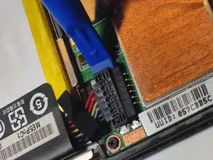
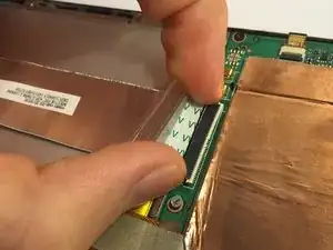
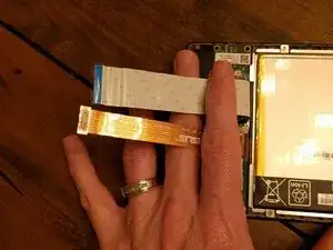
    • Usa l'estremità piatta di uno spudger o le unghie per far scattare l'aletta protettiva trasparente sullo zoccolo ZIF del cavo piatto.

    • Con l'estremità piatta di uno spudger o le unghie, solleva la porzione sottile del connettore (dal lato opposto a dove si inserisce il cavo) per liberare il cavo dal suo zoccolo.

    • Non far leva sullo zoccolo dal lato dove si inserisce il cavo, perché potresti staccare l'intero zoccolo dalla scheda madre.

    • Sfila il cavo dallo zoccolo ZIF.

    • Per maggiori informazioni su come staccare i connettori ZIF, vedi la nostra guida Riconoscimento e scollegamento dei connettori dei cavi.

    Flip up on the WHITE part, facing away from the cable. I sort of struggled with this part, but fortunately didn't do any serious damage.

    yuguoxiong -

    This is the correct way to do it. Flipping up the white part is what you have to do. I tried flipping up the black part and some of it broke off.

    Ryan -

    I found that I had to flip up on the black part here. I broke a section of the white trying to flip it up.

    pattylanter -

    This comment saved me on this step. Indeed the secret is to flip up the black part of the connector, located opposite the side where the cable inserts.

    Hannah Cirimele -

    This is wrong, these comments should be deleted so as to not confuse more people.

    Jeff Andrews -

    It's possible there's more than one color variation in production on these Nexus 7 ZIF sockets. To complicate matters, it looks like the guide's original author/photographer may have simply yanked the ribbon cable out without opening the socket, so there's very little visual clue here as to which is the right section to flip up. Based on these photos, I'd say Hannah's tip is probably correct—you want to flip up the thinner portion of the socket, opposite the cable (regardless of its color scheme). If someone who has successfully completed this step could supply a better photo, that would be super helpful!

    Jeff Suovanen -

    I revised the text so there's no long any mention of the coloration of the socket.

    Jeff Suovanen -

    I believe I broke the ZIF attached to the mobo at this step; is there any other way to reconnect it during reassembly or will I require a new mobo?

    Neil Reed -

    This was my first time with this kind of ZIF socket and found these instructions/pictures ambiguous. In hindsight I see what was being described (actually used the replacement daughterboard as my guide). May I suggest this phrasing:

    The ZIF clamp hinges on the side opposite of where the cable in inserted. Using the flat end of a spudger or your fingernail, flip the thin portion of the connector up and away from the insertion side of the connector.

    charles fineman -

    Correction of Charles' Oct comment: The ZIF clamp hinges on the same side as the cable is inserted, the side towards the battery. The cable runs over the battery and into the thick connector, with contacts both on the side closest to the battery and on the side away from the battery. Beyond the contacts on the side away from the battery is the thin part to be lifted. Using the flat end of a spudger or your fingernail, flip the thin portion of the connector up and towards the insertion side of the connector. You can leverage gently against the big copper-covered area on the side away from the battery, in lifting the thin (white in the current picture) part of the connector.

    ted ballou -

    You can leverage gently against the big copper-covered area on the side away from the battery, in lifting the thin (white in the current picture) part of the connector, using a motion similar to the described in step 5 below for removing the orange ribbon connector.

    ted ballou -

    some better macro photos of the zif socket would help a lot, in closed and open states

    Iain Lennon -

    For anyone like me who has only experience with metal connectors similar to iPhones, this is a "switch-on/switch-off" connector.

    The cable doesn't pop out by itself, you have to pull it out yourself.

    Light to moderate pressure required.

    Jason -

    Please make the pictures clearer as Iain Lennon said. I too was a fool to not read the comments and broke the connector off of the motherboard.

    Yumi Blesh -

    Ha.

    So one side of the cable has a white strip connector, and the other side has a black strip connector. (both comments above are correct, depending on which side you are looking at)

    The side in the photo has a black connector strip that needs to be opened. It is the long small strip of plastic on the _opposite_ side of the connection point, to the cable.

    It clicks up into the air, like on a hinge.

    The cable then pulls out, without any resistance.

    Warwick -

    Having totally destroyed the ZIF connector I can now say that the WHITE portion is hinged and the BLACK portion is not. Both parts are extremely fragile. The photographs are really useless.

    David Spitzer -

    exactly ……..

    esykas -

    This shouldn’t be the first cable to disconnect. Disconnect the battery cable first. Always remove power first!

    dave -

    Good catch @hobohax0r, we rearranged the steps to help fix that!

    Sam Goldheart -

    I have added a photo of the socket in the open state. Also looking at the comments above it seems that the confusion is due to the fact that this cable is connected to a similarly looking connector on the other side, where the colors are reversed. It may be worth to point this out and tell that the connector the guide is talking about is located near the heatsinks

    Michael Sokolkov -

    Be very careful when you reconnect this cable - for some reason my screen would not respond to touch any more if you reconnect the cable on too tightly. Make sure you leave a bit of slack when putting the cable back in, and not just jam it all the way in.

    Mark -

    I tried to take some pictures of the way the sockets worked on mine (2013 Wi-Fi (Flo)), but considering hardware variations, I’m not sure if this applies to every Nexus 7 (or even every Flo)

    https://imgur.com/a/wd8hFqW

    W H -

    Just to follow up, much later… if you see white, you should see a small notch. lift there.

    Look very carefully at the second photo and see the white “flap” has been opened, pointing at you.

    Whichever color, it takes NO REAL EFFORT to flip them back. No need to force anything at this micro level.

    Mike Maddux -

  5. eOfehnJfsHK1GWGI
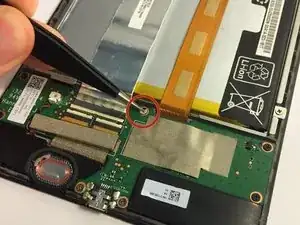
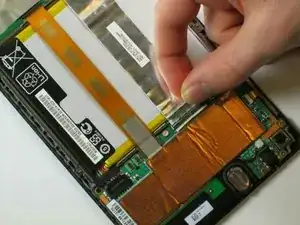
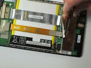
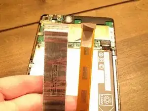
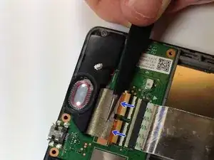
    • Stacca la lamina protettiva disposta sopra la scheda madre per esporre la connessione del cavo flat arancione.

    • Le connessioni del cavo piatto dovrebbero essere perfettamente visibili, mostrando le linguette di plastica.

  6. vVkI6EGxv1JyTBHe
    vVkI6EGxv1JyTBHe
    oB2HWVBCL5NESv6X
    hQSUbJoWIvDTHlRG
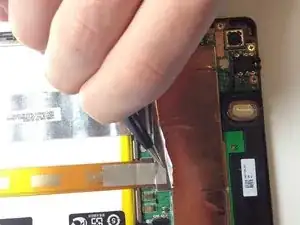
    • Stacca con delle pinzette il foglio protettivo argentato sopra il connettore del cavo a nastro arancione.

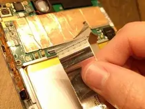
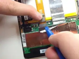
    • Fai leva sotto il connettore del cavo arancione con lo strumento di apertura in plastica per sollevarlo. Dovrebbe saltare via dalla sua posizione.

  7. PtGFmOKWlncKdCK3
    PtGFmOKWlncKdCK3
    mEwQaOo34X5OKrwL
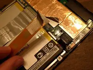
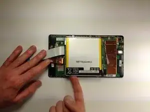
    • Ora che i due cavi piatti principali sono scollegati, ripiegali e tienili lontano con le dita, oppure sistemaci sopra le pinzette o un altro oggetto leggero per tenerle discoste.

    How called is the left one ? I broke it and i will buy it but cant find it..

    Timo Dohmen -

  8. 5JPhFNGmbFcLRehZ
    • Usa il cacciavite a croce Phillips #0 per rimuovere le quattro viti a croce cromate Phillips #0 da 3 mm disposte attorno all'alloggiamento della batteria.

    There are 6 screws on mine. One at the top and the other directly across from that on the other side of the battery at the bottom. These two screws are covered with a small adhesive sticker that says “seal". Those stickers need to be removed so the Phillips screwdriver can be inserted to remove them.

    dabair30 -

    Correcrion, there are 7. One more at the top left corner of the battery tray. The last 3 screws are slightly larger than the first 4.

    dabair30 -

    I found using a #00 Philips worked better for my removal.

    Todd -

    The WIFI only one is exactly as pictured. The LTE one has 3 more screws, two are the motherboard mounting screws (one with tamper sticker) and one at bottom on the other mainboard (also with tamper sticker). Other than that it is exactly the same.

    dick -

  9. FPOpL14uHChGauin
    • Rimuovi la batteria dal dispositivo esercitando una certa pressione alla base della batteria e quindi sollevandola.

    If your replacement battery doesn’t have the metal battery tray included (like mine came) be aware you’ll have to CAREFULLY pry the old battery out of the metal tray. It has some pretty strong glue holding it in, but prying on it slowly and carefully should get it free without bending up the metal tray. There should be enough glue residue left in the tray to hold the new battery in, at least until you get the tablet back together.

    Tracy Nash -

    Thank you for the very helpful comment - I was facing the same issue!

    Jorge Gomes -

    You probably should add that the battery is held in the tray with some glue strips. It took a bit to carefully remove the battery from the tray without bending the tray too much. Also, the replacement battery I had was slightly smaller than the OEM battery. When putting back together make sure you place the battery in the tray so the battery is close enough to the battery connector and you can reconnect the battery without pulling on the connector wires.

    Todd -

    Having replaced the battery I find it doesn't charge. Which connector could be at fault please?

    mxclubman -

  10. VVhUnKTCDfZ1mVQX
    VVhUnKTCDfZ1mVQX
    hXVPSh5RmYlrpvNi
    • Rimuovi il sigillo grigio che copre la vite superiore centrale sulla scheda figlia.

    • Sappi che questa azione invaliderà la garanzia sul dispositivo.

    • Vedi di riporre il sigillo in un posto dove non si sporchi e possa mantenere la sua adesività.

    I couldn't get a grasp on the sticker enough to peel it off, so just punched through it with the screwdriver. I don't know the point of removing the sticker, since the warranty is voided anyway by either time or the mere act of disassembly.

    yuguoxiong -

    How come the battery is still in place in the picture? I couldn't get the battery out until I'd removed another 3 screws...1 on the daughterboard (step 11) and 2 on the motherboard (step 16).

    Mark Birbeck -

    Both hidden screws were holding the battery tray in place. I was not able to remove the battery as described in step 9 before removing the screw from this step

    coutureg -

    If you are replacing just the main board and not the daughterboard , I skip this part and go to step 16.

    danovila -

    There actually is no need to remove the daughter board and everything like that. Mother and daughterbord can be taken off at the same time, together with speakers and kept together by the WIFI cables, if you only need replacing the screen

    This guide is still value-for-the-money if you need all the other tricky little details

    Luca Ciminelli -

  11. XTcw1OCV6UNVWZoe
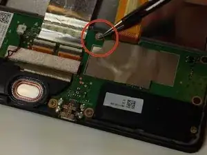
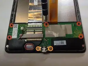
    • Con un cacciavite a croce Phillips #0, svita le cinque viti nere da 2 mm tutto attorno al bordo della scheda figlia.

    • Usa lo stesso cacciavite Phillips #0 per rimuovere due viti cromate da 3 mm da ciascuna lato della micro USB.

    Is there a reason you suggested removing the screws at this point? I found it to be more of a hassle having the board moving around as I did the next several disconnects. Unless there's a good reason, I would suggest leaving the screws in until the foam and the connectors have been detached.

    charles fineman -

  12. LpKnPEQ33Q3SYMBy
    LpKnPEQ33Q3SYMBy
    FThwVZvlFocbopvv
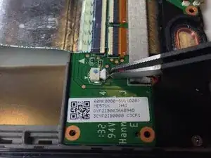
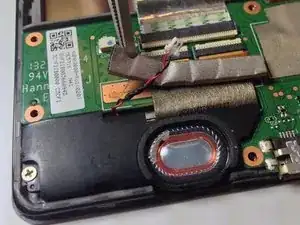
    • Usa delle pinzette per scollegare dalla scheda figlia il connettore dell'altoparlante, spingendolo lateralmente.

    • Questa operazione richiede delicatezza perché questo connettore può essere fragile. Non tirare verso l'alto.

  13. RTSht35Wkefk6URY
    • Con delle pinzette, stacca lentamente la cover attaccata sul connettore a pin.

  14. yGkbH2lGExCPSNVM
    yGkbH2lGExCPSNVM
    hro6KqxYR2S2ySNm
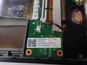
    • Usa l'estremità piatta di uno spudger o un'unghia per sbloccare con delicatezza le due alette di bloccaggio di ciascuno zoccolo ZIF.

    • Nel disconnettere le prese ZIF, spingile fuori rispettivamente in direzione del bordo della scheda e verso i cavi.

    • Stai attento non danneggiare il connettore a pin. Tira parallelamente al dispositivo e non verso l'alto.

    • Per maggiori informazioni su come staccare i connettori ZIF, vedi la nostra guida Riconoscimento e scollegamento dei connettori dei cavi.

    Flip up on the WHITE part, facing away from the cable. I sort of struggled with this part, but fortunately didn't do any serious damage.

    yuguoxiong -

  15. EuohW4ctP3WvDfFA
    • Ora è facile sollevare e rimuovere la scheda figlia.

    • Fai attenzione in fase di rimontaggio. Questa scheda figlia una parte molto sensibile. Se le connessioni non sono fatte nel giusto ordine, è facile "bruciare" la parte del digitizer di questa scheda. Completa le connessioni tutti gli altri cavi prima di collegare il tutto all'alimentazione.

Conclusione

Per rimontare il tuo dispositivo, segui queste istruzioni in ordine inverso.

Simon Krauter

Membro da: 22/01/15

1752 Reputazione

11 commenti

Hi,

I need to replace USB connector on my Nexus7-2013 wifi, buit I had see on ASUS web site, if I change this spart, i need to recalibrate the unit .http://www.asusparts.eu/fr/Asus-90NK0080...

Is it true ?

Thx for your answer

Vincent PONS -

According to these repair stories, it worked fine without any mentions of a need to calibrate: Nexus 7 (2nd Gen Wi-Fi) LCD Board

beanthedemon -

Great guide, easy to follow, the only input I would add is that stating which direction the zif connectors open would be helpful for newbies like me :)

lyleinnes -

Hello i have a problem with a spudger in the daughter board, i crashed one of them will replacing the screen, i need to know how to fix it or the best place to buy a used daughter board

Hady Allam -

My nexus 7 2013 wifi is charging fine with the existing board, but when I connect it to PC, it doesn't open the USB connection. Now, do I get the replacement or is this is a software bug?

manohar.m -

Try a different USB cable.

beanthedemon -

I posted this in the Q/A section but I thought I'd post here.

I purchased a replacement USB board on Amazon provided by ifixit for my Nexus 7 (2nd Gen) tablet. The installation was easy, but after turning on my tablet the left half of the screen would not respond to touches. Charges fine though (which is why I bought the part). I let the tablet charge then I swapped the old part back in. Viola! Screen works fine. Is there another step I need to perform with this new part or should I send it back for replacement?

Answer your question

gchildt -

I just replaced mine. Just make sure to check the version number on the board before ordering the replacement. Mine was Rev 1.4. If you get one with a different rev your screen will not work. Unfortunately the rev number is on the back of the board so you’ll have to remove it first.

The first larger ziff connector the black part flips up and forward towards the top of the tablet. The two smaller ones the white part flip up and back towards the bottom of the unit.

I found that I did not have to remove the battery first. There’s small bit of metal near the edge of the board. Once the screws are out of the board it will slide down enough to let you slip it from under the metal.

E T -

Great guide… thanks! I just replaced my daughterboard, but when I fired back up, my touchscreen doesn’t respond to touch. Charge is good… usb connection is good… screen looks good… but no touch.

Any thoughts?

Thanks!

Russell

Russell Spurlock -

update… must be the chip on the new board because when I put the old one back in, the touchscreen works immediately

Russell Spurlock -

My device only charges when it’s turned off. What would be the specific replacement part I’d need to order? I’d guess I only have to buy the charging assemble?

joser1813 -