
Introduzione
Segui questa guida per sostituire la pulsantiera in gomma conduttiva e i pulsanti di accensione e volume esterni.
La Switch utilizza viti di tipo JIS, ma è possibile utilizzare un cacciavite a croce Phillips in caso di necessità. Fai molta attenzione a non danneggiare le viti. Le punte a croce di iFixit sono progettate per essere compatibili con le viti di tipo JIS.
Quando effettui la reinstallazione, attacca i pulsanti di plastica esterni al pad di gomma conduttivo e inseriscili insieme nel dispositivo.
Nota: Questa guida, e il componente che vendiamo, sono compatibili con il modello originale di Nintendo Switch rilasciato nel 2017, così come con il modello rinnovato più recente rilasciato nel 2019 (rispettivamente con i numeri di modello HAC-001 e HAC-001(-01)).
-
-
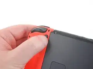
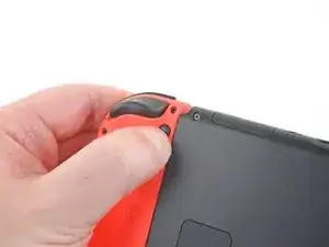
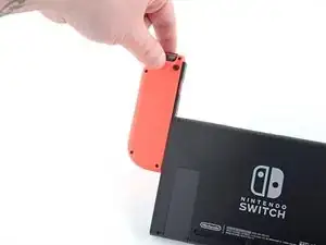
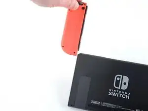
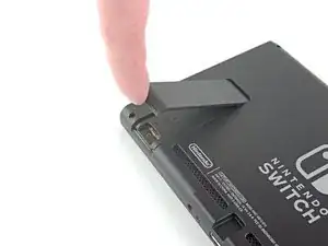
Premi e tieni premuto il piccolo bottone rotondo dietro il controller Joy Con.
-
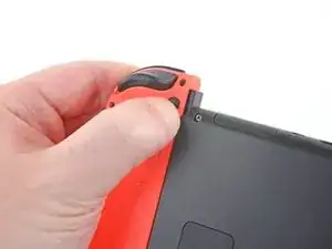
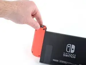
Mentre tieni il bottone premuto, fai scorrere il controller verso l'alto.
-
-
-
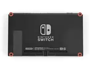
Usa un cacciavite Y00 per rimuovere le quattro viti lunghe 6,3 mm che tengono fermo il pannello posteriore.
-
-
-
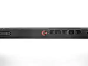
Usa un cacciavite JIS 000 o quello PH 000 ufficiale di iFixit per rimuovere le seguenti viti che fissano il pannello posteriore:
-
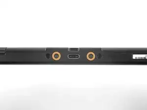
Una vite lunga 2,5 mm sul bordo superiore del dispositivo
-
Due viti lunghe 2,5 mm sul bordo inferiore del dispositivo
-
-
-
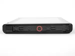
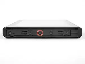
Usa un cacciavite JIS 000 o quello PH 000 ufficiale di iFixit per rimuovere le due viti centrali da 3,8 mm ai lati del dispositivo (una per lato).
-
-
-
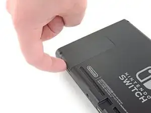
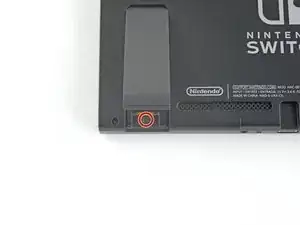
Usa il tuo dito per ruotare verso l'alto il cavalletto sul pannello posteriore del dispositivo.
-
-
-
Usa un cacciavite JIS 000 o quello PH 000 ufficiale di iFixit per rimuovere la vite da 1,6 millimetri nella sede del cavalletto di supporto.
-
Chiudi il cavalletto.
-
-
-
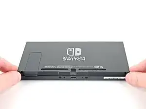
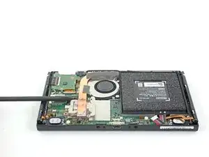
Solleva il pannello inferiore dal lato posteriore del dispositivo e rimuovilo.
-
[*icon_note] Il cavo di collegamento del lettore di cartucce è collegato all'altra metà della scocca di plastica impedendoti di sollevare completamente il pannello posteriore se chiuso.
-
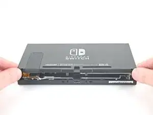
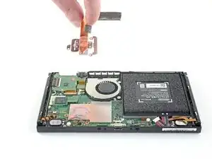
Solleva il pannello posteriore dal fondo del dispositivo e rimuovilo
-
-
-
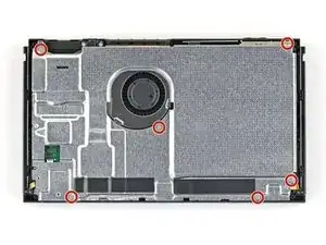
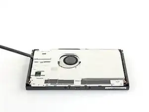
Con un un cacciavite a croce JIS 000 o quello PH 000 ufficiale di iFixit, rimuovi le sei viti da 3 mm dalla piastra di schermatura.
-
-
-
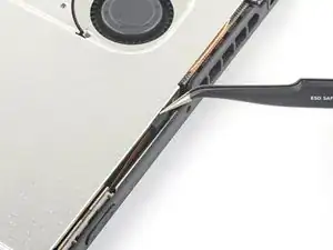
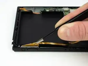
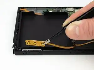
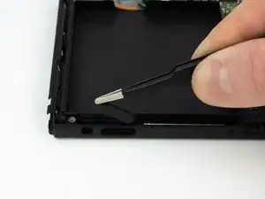
Usa un paio di pinzette per staccare il pezzo di schiuma sul bordo superiore del dispositivo vicino alla porta di scarico della ventola.
-
[* icon_caution] Se non riesci facilmente a staccare la schiuma, non forzarla! Potrebbe strapparsi facilmente. Sollevala cautamente da più punti fino a staccarla.
-
-
-
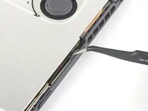
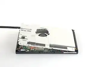
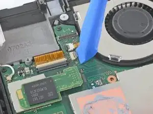
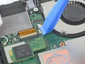
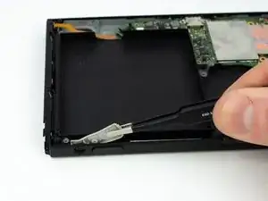
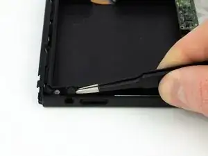
Inserisci uno spudger sotto la piastra di schermatura lungo i bordi.
-
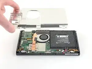
Fai leva per sollevare con delicatezza la piastra di metallo e rimuovila dal dispositivo.
-
Puoi riutilizzare la pasta termica rosa se sei attento. Mantieni pulita la pasta e assicurati che faccia un contatto solido tra il dissipatore di calore e la piastra durante il rimontaggio.
-
Se devi sostituirla, consulta la nostra guida sulla pasta termica per rimuovere quella vecchia e sostituirla con una pasta termica appropriata, come la K5 Pro, durante il rimontaggio.
-
-
-
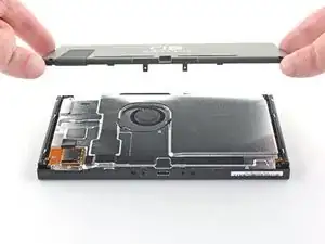
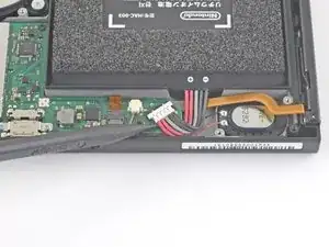
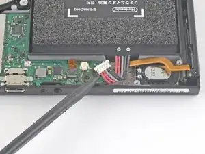
Inserisci l'estremità a punta di uno spudger per far leva e sollevare il connettore della batteria dal suo zoccolo sulla scheda madre.
-
-
-
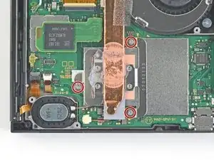
Usa un cacciavite a croce JIS 000 o quello PH 000 ufficiale di iFixit per rimuovere le tre viti da 3 mm che fissano il dissipatore alla scheda madre.
-
-
-
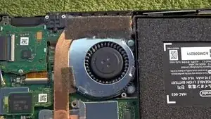
Cautamente stacca dalla ventola i due pezzi di schiuma incollati sul dissipatore e sulla ventola.
-
Inserisci la punta di uno spudger sotto la parte di schiuma che non è a contatto con nulla.
-
Premi il lato superiore della schiuma con un dito per tenerla ferma.
-
Ruota la punta dello spudger sotto la schiuma fino all'altra estremità per staccarla.
-
-
-
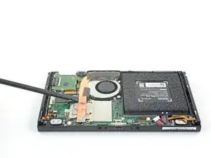
Usa uno spudger o le dita per sollevare il dissipatore verso l’alto e in direzione opposta alla scheda madre, per rimuoverlo.
-
Applica della pasta termica a tutte le superfici che l'avevano precedentemente, anche tra il tubo e la schermatura in alluminio, che la Switch utilizza come dissipatore aggiuntivo.
-
-
-
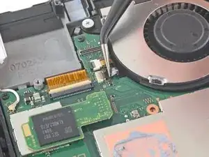
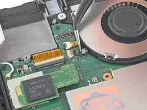
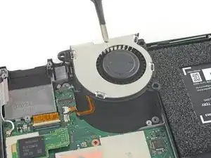
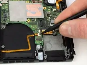
Usa uno strumento di apertura, uno spudger o un'unghia per sganciare l'aletta grigia di bloccaggio del connettore ZIF che tiene fissato il cavo della ventola.
-
-
-
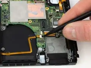
Usa un paio di pinzette per tirare fuori dal connettore sulla scheda madre il cavo della ventola.
-
-
-
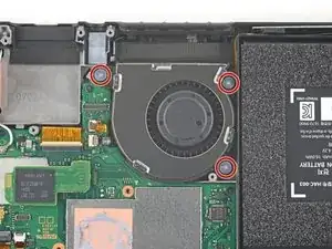
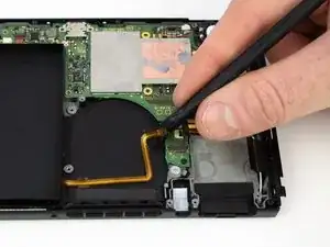
Usa un cacciavite a croce JIS 000 o quello PH 000 ufficiale di iFixit per le tre viti da 4,8 mm che tengono ferma la ventola.
-
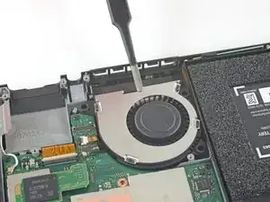
Per riassemblare il dispositivo, segui le istruzioni in ordine inverso.

3 commenti
What happens if the small black locking flap breaks?
Two angles are congruent if they have the same measure. You already know that when two lines intersect the vertical angles formed are congruent. You have also seen that if ∠A and ∠B are each complementary to ∠C, then ∠A ~= ∠B. There are other angle relationships to explore. When you expose these angle relationships, you will establish their truth using a formal proof.
Qui Ma -
This guide is missing the steps to Remove the microSD card reader and the steps to Remove the headphone jack and game card reader
Kann ich diese Anleitung auch für die OLED anwenden? Habe im INet sonst leider nichts brauchbares gefunden.
Ina Barz -
backup all your sd card data i had to format mine after this tutorial and lost all my game data
JustForThisComment?ComeOn -