Introduzione

Questa guida ti aiuterà a sostituire la custodia del Joy-Con sinistro sulla tua Nintendo Switch (modello HAC-015).

Se la custodia del tuo Joy-Con è rotta o scolorita, potresti voler sostituirla. La custodia del Joy-Con protegge le sue componenti interne mentre fornisce anche una piacevole estetica. Una custodia rotta prima o poi danneggerà anche le componenti interne e può anche essere scomoda da impugnare.

Puoi trovare le coperture di ricambio su Amazon, Dove sono molto più economiche che acquistandole direttamente da Nintendo. Queste sono di diversi colori e con diverse stampe.

Mentre segui questa procedura, assicurati di non spanare nessuna vite o rimuovere alcuna componente facendo troppa forza. Qualsiasi piccolo danno può causare un malfunzionamento del tuo Joy-Con.

Se vuoi anche sostituire la custodia del Joy-Con destro, c'è un'utile guida su iFixit che ti può illustrare la procedura.

  1. b5coIjciEm6YXOXx
    b5coIjciEm6YXOXx
    yoxiQFnvilyUUmeP
    • Inizia svitando le quattro (4) viti tri-wing ("Y00") dal pannello posteriore.

    • Conserva le viti in un posto sicuro e organizzato.

  2. NVtbrSokfYsVjoEQ
    NVtbrSokfYsVjoEQ
    mCTgSXiuMZhb4dem
    YbA5HtHJ5GDneDZC
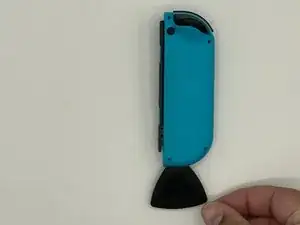
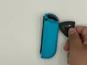
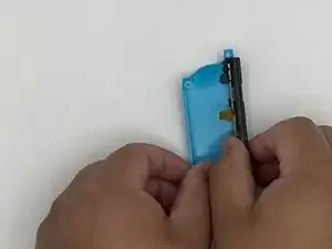
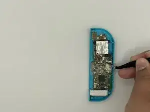
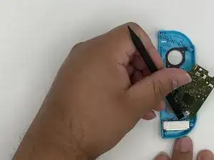
    • Infila un plettro nella fessura sul bordo inferiore del controller (quello dalla parte opposta dei tasti L e ZL).

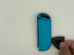
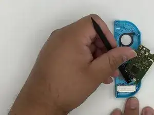
    • Fai scorrere lentamente il plettro lungo il bordo del Joy-Con.

  3. LwlLVNRoDXquQiOh
    LwlLVNRoDXquQiOh
    Yawr1RDyfFWlcawv
    • Tenendo la guida di ricarica rivolta lontana da te, apri il Joy-Con come un portatile.

    • Non rimuovere ancora del tutto la custodia posteriore: ci sono ancora due cavi a nastro che collegano la guida alla scheda madre.

  4. AlfR4Df4iuZfavrB
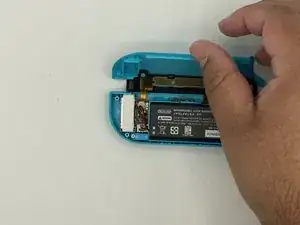
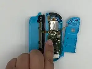
    • Solleva delicatamente il connettore della batteria dritto dalla sua presa sulla scheda madre utilizzando uno spudger di plastica (evita quelli metallici per ridurre il rischio di cortocircuitare i componenti). Ciò impedirà al Joy-Con di accendersi durante la riparazione.

    • Fa' attenzione quando lavori intorno al cavo del modulo di vibrazione, che si trova nelle vicinanze del connettore della batteria.

    • Quando si maneggiano componenti elettronici e/o batterie, è una buona idea indossare almeno un braccialetto antistatico.

  5. xLfdJHhqkRcQoQCM
    xLfdJHhqkRcQoQCM
    o3qgiTMIBDgrEgNe
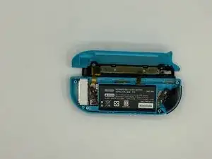
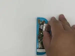
    • Infila lo spudger tra la batteria e la custiodia del Joy-Con.

    • Fai leva delicatamente per sollevare la batteria.

    • La batteria è tenuta ferma da un leggero biadesivo.

    • Stai attento a non deformare, forare o danneggiare la batteria.

  6. PvACKOGpq166qArM
    • Svita le tre viti Phillips #00 dorate da 3,5 mm dal telaio intermedio.

  7. O1BVHVbJQy5fFqTA
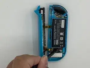
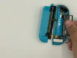
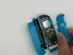
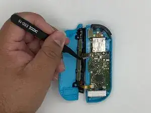
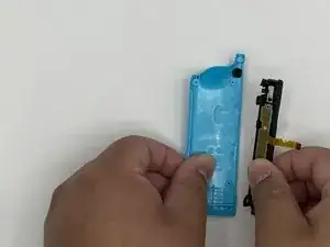
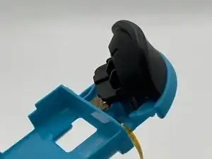
    • Ruota attentamente di fianco il telaio intermedio, lontano dalla scheda madre, come se stessi aprendo un libro.

    • I cavi a nastro sono molto delicati. Si consiglia di utilizzare pinzette non appuntite anziché mani nude.

  8. WvNafavxDB6aUZTv
    WvNafavxDB6aUZTv
    IeFdYnCwmP4JC3F6
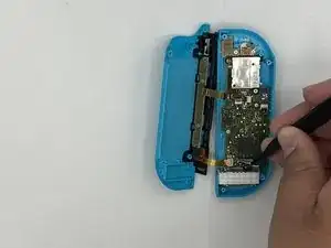
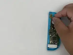
    • Usa delle pinzette per ruotare l'aletta di bloccaggio sul connettore ZIF dalla parte opposta al cavo.

    • Il tasto ZL è tenuto fermo da un piccolo connettore ZIF sulla scheda madre.

    • Usa le pinzette per sfilare delicatamente il cavo a nastro del tasto ZL dalla sua presa. Il telaio intermedio è ora scollegato e può essere rimosso.

  9. x2ELyImMI4ajeNMP
    x2ELyImMI4ajeNMP
    vDqeivuOXeRvYrSY
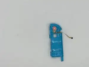
    • Sblocca il connettore ZIF superiore della guida e scollega il cavo.

    • Sblocca il connettore ZIF inferiore della guida e scollega il cavo. Ora puoi rimuovere la guida dalla custodia posteriore.

    • Rimuovi il tasto L e la sua molla.

    • Stai attento in quanto la molla tende a schizzare via.

    Details for removing the ZL trigger are Step 12

    Luke Lucas -

    I think this guide mean L button and spring instead of ZL button since that is attached to the mid frame which was removed before this step.

    Callum M. -

  10. 6m56f4BKPWTQGVN2
    6m56f4BKPWTQGVN2
    PPo4YBtWCMdsJaXL
    PU4uocWTAjJR3Wty
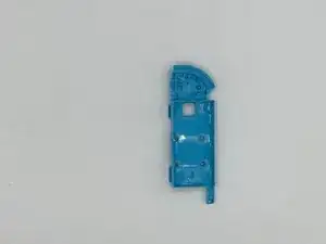
    • Svita la vite che tiene ferma la guida. Rimuovi la guida dalla custodia posteriore e mettila da parte.

    Screw is Philips #00 as well

    Doc Halstater -

  11. AZGx6ZuWkqoBv5gW
    • Rimuovi il tasto di bloccaggio e mettilo da parte.

  12. 3nTkswaKYUADclih
    3nTkswaKYUADclih
    TnoxA1dRSJdVmFE6
    • sblocca il fermo sotto il grilletto usando delle pinzette. Rimuovi delicatamente il grilletto.

    • Assicurati di segnarti la posizione delle due molle sotto il grilletto in quanto devono essere rimontate nella stessa posizione sul nuovo telaio intermedio.

    Ahh nevermind. Figured this one out via brute force. Press and hold near the bottom of the trigger button—to keep the springs from flying away—then use a prying tool (I used a flat pick) to separate the top of the button from the midframe. The trigger button is held in place from behind with two circular indentations near the top of the button. Pry the button straight away from the midframe to release them.

    synthmage -

  13. ehlggYmVsBpUTYMr
    ehlggYmVsBpUTYMr
    jUGp232rXjufQxeX
    • Svita la vite che tiene ferma la scheda del grilletto.

    • Rimuovi la scheda del grilletto.

  14. jyvAkZdrM4mG4g24
    jyvAkZdrM4mG4g24
    oKFNQTWWUxbwqfPe
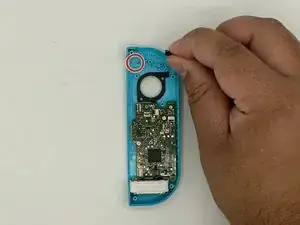
    • Svita le viti che tengono ferma la levetta analogica.

    • La vite in alto a sinistra è coperta dal cavo flessibile del pulsante L.

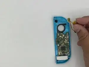
    • Sblocca il connettore ZIF e scollega il cavo a nastro con delle pinzette.

    Unlock the ZIF connector and release the ribbon on the left that is covering a screw before attempting to remove the screws

    Luke Lucas -

  15. GYOLho24y4pMUNIi
    GYOLho24y4pMUNIi
    oEgjnviILWoJw1hs
    • Rimuovi la levetta analogica.

  16. cWVFKBZZ2XsUCWog
    cWVFKBZZ2XsUCWog
    AwnKCBKAPyQNFoFL
    ZokQHYefNPKqksK2
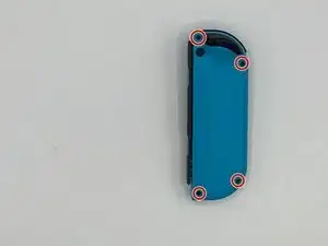
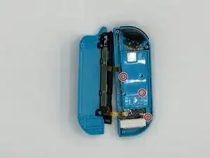
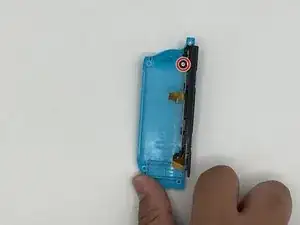
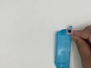
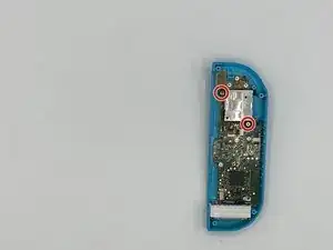
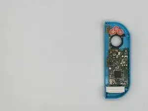
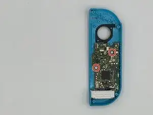
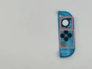
    • Rimuovi le viti che tengono fermo il circuito flessibile (contrassegnate da un cerchio rosso) per i pulsanti meno e L.

    • Rimuovi il circuito flessibile.

  17. 6adyooKy3XsRtpgW
    • Rimuovi il tasto meno.

    • Ci sarà una membrana di silicone sopra il tasto meno. Assicurati di rimetterla al suo posto durante il rimontaggio.

  18. BgBuGfAMwMtWOiPX
    • Svita le viti che tengono ferma la scheda madre.

  19. iLjRd6qI4cALUa34
    iLjRd6qI4cALUa34
    AN6broLjJkiIJLTf
    2PJtLPrPsEdvoBVg
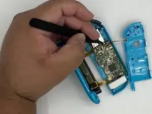
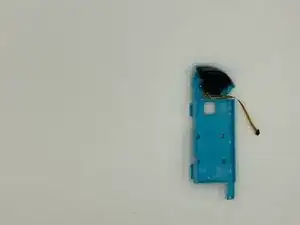
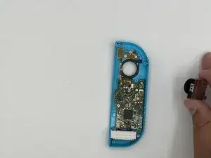
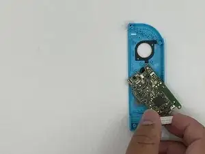
    • Usando un spudger, fai leva sul motore della vibrazione per sollevarlo dal suo alloggio.

    • Rimuovi il motore della vibrazione e la scheda madre.

  20. eL6gqGdSYOwLvWKy
    • Rimuovi i cinque tasti restanti dalla custodia.

Conclusione

Per rimontare il dispositivo, segui le istruzioni in ordine inverso.

Jose Castro

Membro da: 16/01/20

917 Reputazione

11 commenti

This guide was very helpful! A picture of the latch location on the trigger (step 12) would have been a big help, that step took a minute because I was putting pressure on the wrong spot.

I also noticed that most of the #00 screws were more receptive to a J00 bit. Might be worth noting in the tools section since swapping between them can strip a screw.

Fitz Montville -

Used this guide for reference on the tools needed, someone else pointed out to use the J00 bit instead of the P00 and I’ll second that as the fit for the screws was much better, thanks for the guide much appreciated!

Lee Whittaker -

Exactly what I needed! Dropped a set of controllers on a tile flow and the rail popped out and pulled the ribbon cables too. I picked up another iFixit toolkit with some J bits to put it back together. I don’t know why I waited this long to fix it. Charged the controllers overnight and I’m up another set now!

energy96 -

Others above have mentioned that they needed to use a J00 bit instead of P00, but mine did not work with a J00 and was better with a P000

Jeremy Johnson -

Small thing. In the tools list, it incorrectly says Y0 while the rest of the post correctly says Y00 for the back screws.

William Doering -

Thanks!

Just need a review for add the instructions for removing the L button, between steps 8 and 9 ;)

kazulius -

Nicht ohne Lupe, Pinzette und Spudger als Brillenträger an diese Reparatur gehen. Die Verbindungen der Flachkabel sind verdammt klein. Eine Gute Anleitung. Hat bei mir funktioniert!

Gerd Paßmann -

I followed these instructions and everything works perfectly except my Switch doesn't think the joycon is attached anymore; it thinks I'm using it wirelessly even though it's docked into the system. Any advice?

Dani Watson -

It means you did not situate your Joycon rail correctly, since it does not “click” with the console. Take it apart, make sure the detach button and rail ribbons are secure, readjust, and reassemble your controller

James Conklin -

Please help...

So I followed the instructions step by step, however now the left joy con does not want have a connection status on the switch, it thinks it is disconnected.

Leonard -

Great guide, used it to mod my shell and replace the thumbstick at the same time. The only thing I would say is that if you are replacing the rail and slide locks you'll need a bit of extra guide via YT or something (not sure if there is one on here.) As others have said 'depress the latch' for the ZL button is tricky (kind of just pulled about on mine until it came off, still not sure where the latch is.) And one final thing, it says ZL button at one point but ZL is a trigger - they mean the Z button. But again, great guide, far less issues than expected - thank you to the author.

Luke Lucas -