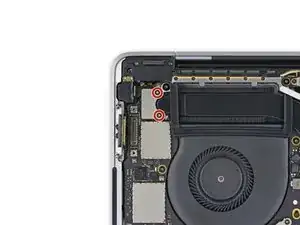
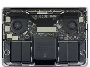
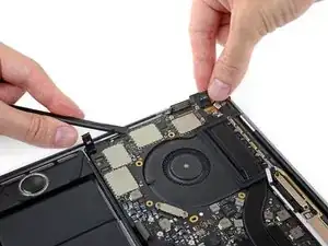
Introduzione
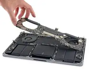
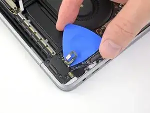
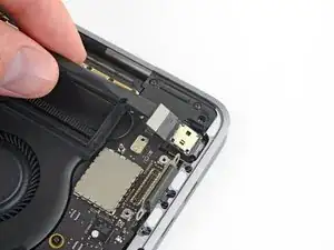
Guida solo prerequisita: rimuovi la scheda logica e il dissipatore termico come un tutto unico, per poter continuare lo smontaggio o semplicemente per evitare che diano fastidio.
-
-
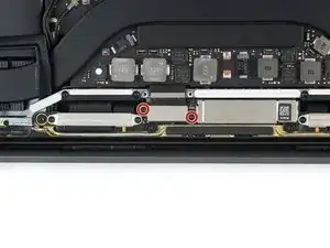
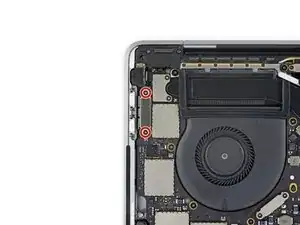
Usa un cacciavite Torx T3 per rimuovere le due viti da 1,9 mm dalla staffa del connettore della tastiera.
-
-
-
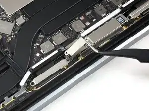
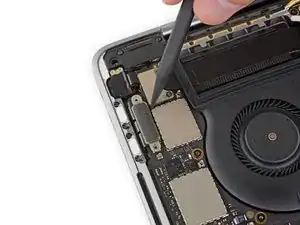
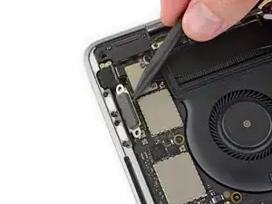
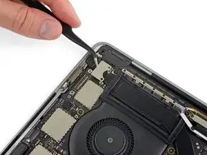
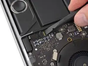
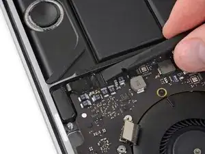
Usa uno spudger per scollegare il connettore della tastiera facendo leva e sollevandolo dalla scheda logica.
-
-
-
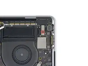
Rimuovi le due viti Torx T3 da 2,9mm che assicurano la protezione in alluminio sopra al cavo principale dello schermo.
-
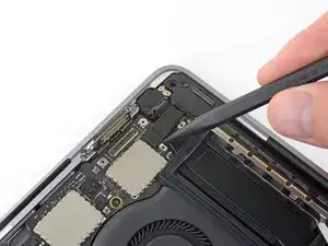
Rimuovi la protezione in alluminio.
-
-
-
Rimuovi le due viti Torx T3 da 1,7 mm che fissano la copertura in alluminio sopra il connettore flessibile del cavo del display.
-
Rimuovi la copertura.
-
-
-
Usa un cacciavite Torx T3:
-
Rimuovi due viti da 1,4 mm dalla staffa del connettore della porta Thunderbolt di sinistra.
-
Rimuovi altre due viti da 1,4 mm dalla staffa del connettore della porta Thunderbolt di destra.
-
-
-
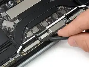
Usa uno spudger per scollegare il connettore della porta Thunderbolt sul lato sinistro facendo leva e sollevandolo dalla scheda logica.
-
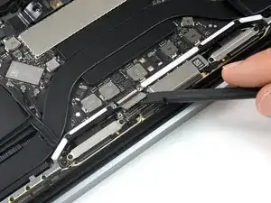
Spingi delicatamente il connettore da un lato in modo che non interferisca con la successiva rimozione della scheda logica.
-
-
-
Ripeti l'operazione precedente per il connettore della porta Thunderbolt sul lato destro, facendo leva dal bordo interno; una volta scollegato, spingilo delicatamente da una parte.
-
-
-
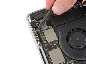
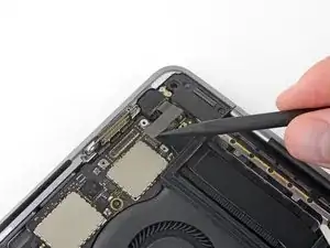
Usa un cacciavite Torx T3 per rimuovere le due viti da 1,9 mm dalla staffa di copertura che fissa il Touch ID e i connettori audio tipo jack da 3,5 mm.
-
-
-
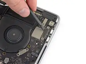
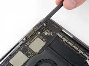
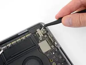
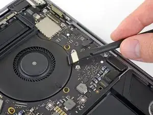
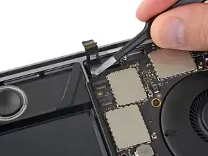
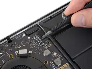
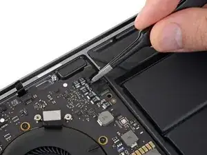
Usa uno spudger per disconnettere il cavo flessibile del jack audio da 3,5 mm sollevandolo dalla scheda logica.
-
Spingi delicatamente verso l'esterno il cavo flessibile.
-
-
-
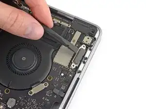
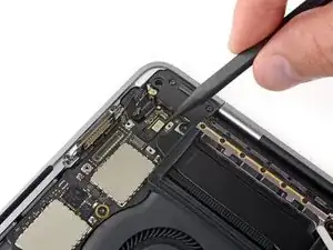
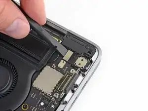
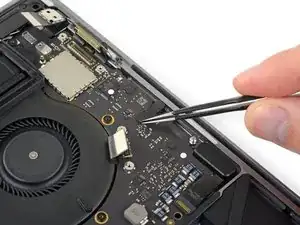
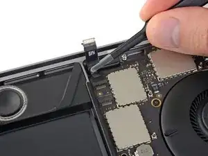
Disconnetti il cavo flessibile del Touch ID e del pulsante di accensione facendo leva per sollevarlo dalla scheda logica.
-
-
-
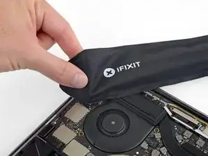
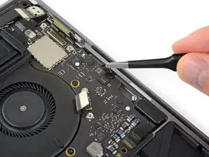
Applica una quantità modesta di calore con un iOpener, una pistola termica o un asciugacapelli per ammorbidire l'adesivo sotto il cavo flessibile del Touch ID e dell'accensione.
-
-
-
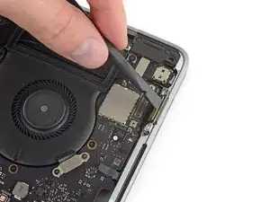
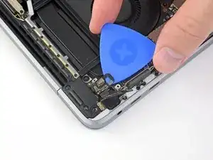
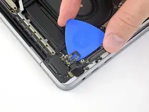
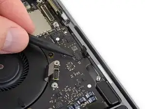
Fai scorrere con cautela un plettro di apertura sotto il cavo flessibile per separarlo dalla scheda logica, quindi spingi delicatamente il cavo verso l'esterno.
-
Se hai dei problemi, non forzare: applica ancora un po' di calore e prova di nuovo.
-
-
-
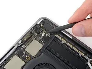
Usa un cacciavite Torx T3 per rimuovere la vite da 1,9 mm dalla staffa del connettore del digitizer del Touch Bar.
-
-
-
Usa uno spudger per scollegare il digitizer del Touch Bar facendo leva sul suo connettore per sollevarlo dalla scheda logica.
-
-
-
Usa un cacciavite Torx T3 per rimuovere due viti da 1,9 mm dalla staffa del connettore del display del Touch Bar.
-
-
-
Usa uno spudger per scollegare il connettore del display Touch Bar facendo leva sotto di esso per sollevarlo dalla scheda logica.
-
-
-
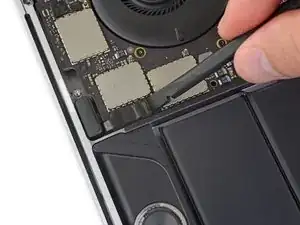
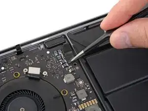
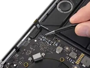
Apri l'aletta di bloccaggio del connettore ZIF del cavo del microfono sollevandola dalla scheda logica.
-
-
-
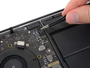
Disconnetti il cavo del microfono tirandolo all'indietro (allontanandolo dalla ventola) finché non scorre fuori dal suo zoccolo.
-
Se possibile, non tirare sul cavo ma sul nastro attaccato al cavo stesso.
-
-
-
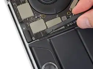
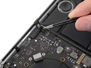
Fai scattare in posizione aperta l'aletta di bloccaggio del connettore ZIF del tweeter del lato sinistro sollevandola dalla scheda logica.
-
-
-
Disconnetti il cavo tirandolo verso il tweeter finché non scorre fuori dal suo zoccolo.
-
Se possibile, tira sul nastro attaccato al cavo invece che sul cavo stesso.
-
-
-
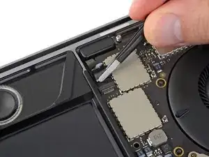
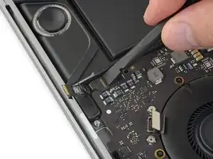
Fai scattare in posizione aperta l'aletta di bloccaggio del connettore ZIF dell'altoparlante principale di sinistra sollevandola dalla scheda logica.
-
-
-
Disconnetti il cavo dell'altoparlante principale di sinistra tirandolo verso il tweeter finché non si libera dal suo zoccolo.
-
Vedi di tirare sul nastro attaccato al cavo e non sul cavo stesso.
-
-
-
Ripeti i sei passi precedenti per scollegare il tweeter e l'altoparlante principale del lato destro.
-
Inizia staccando il nastro adesivo che copre il connettore del tweeter.
-
-
-
Fai scattare in posizione aperta l'aletta di bloccaggio del connettore ZIF del tweeter del lato destro sollevandola dalla scheda logica.
-
-
-
Disconnetti il cavo tirandolo verso il tweeter finché non scorre fuori dal suo zoccolo.
-
Ricordati, se possibile, di tirare sul nastro e non sul cavo.
-
-
-
Fai scattare in posizione aperta l'aletta di bloccaggio del connettore ZIF dell'altoparlante principale di destra sollevandola dalla scheda logica.
-
-
-
Disconnetti il cavo dell'altoparlante principale di destra tirandolo verso il tweeter finché non si libera dal suo zoccolo.
-
-
-
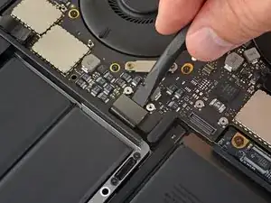
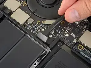
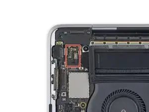
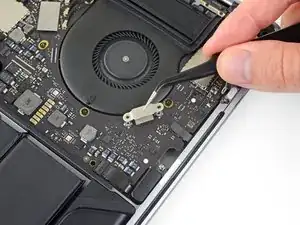
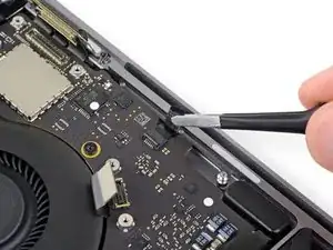
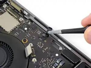
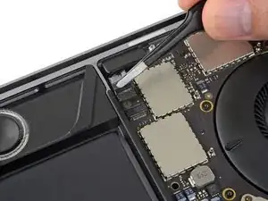
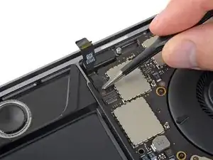
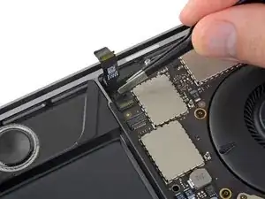
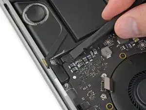
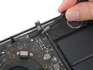
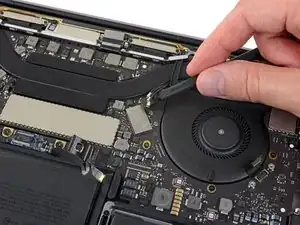
Disconnetti il primo cavo di antenna sollevandolo dal suo zoccolo.
-
Fai scorrere con cautela delle pinzette o l'estremità piatta di uno spudger sotto il cavo finché non arrivi vicino allo zoccolo e a quel punto tira verso l'alto oppure fai leva per disconnettere il cavo.
-
-
-
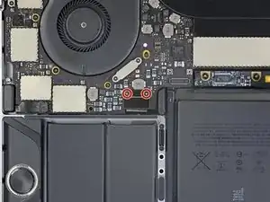
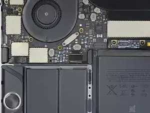
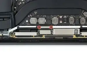
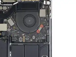
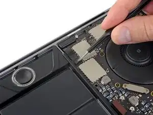
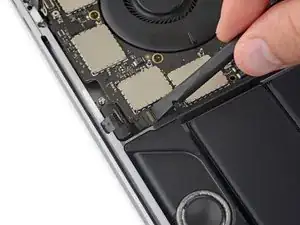
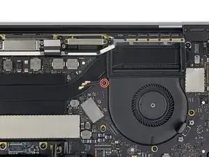
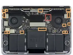
Rimuovi tutte le dieci viti che fissano il gruppo della scheda logica:
-
Tre viti Torx T3 da 2,5 mm
-
Cinque viti Torx T5 da 2,9 mm
-
Due Torx T5 da 3,0 mm
-
-
-
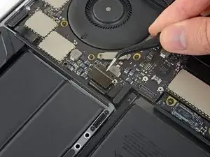
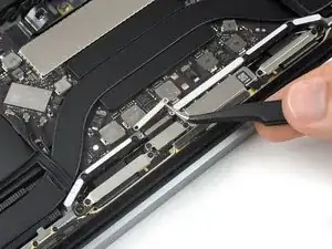
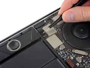
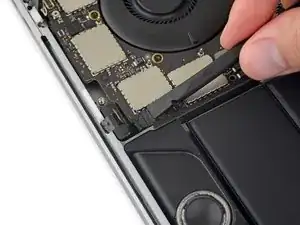
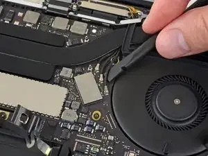
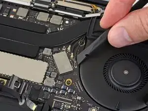
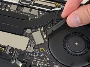
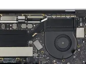
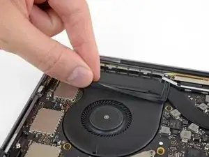
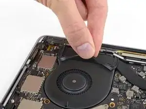
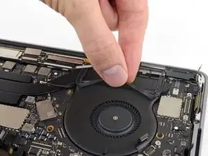
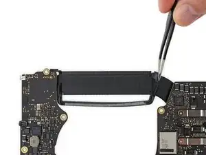
Stacca, ma senza rimuoverle completamente, le due strisce antivibrazione in gomma dall'adesivo che le tiene collegate alle ventole.
-
Se necessario, applica una modesta quantità di calore con un iOpener, un asciugacapelli o una pistola termica per ammorbidire l'adesivo e rendere più facile staccare le strisce.
-
-
-
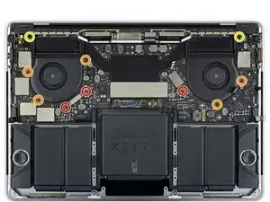
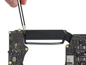
Controlla l'allineamento dei supporti antivibrazione in gomma e disponili nella giusta posizione.
-
Fai passare l'insieme del cavo di antenna nella fessura tra la scheda logica e il dissipatore di calore e accertati che sia correttamente allineato nel momento in cui abbassi la scheda per disporla nella sua posizione.
-
Verifica che non ci siano cavi intrappolati sotto la scheda mentre la installi. Controlla con cura tutte le posizioni indicate.
-


Per rimontare il tuo dispositivo, segui queste istruzioni in ordine inverso.

Un commento
Microphoneのパーツの説明欄には、Teardownの動画がリンクされていますが、その動画にはMic部分の説明が無いため、このページをリンクしておくと良いと思いました。
This page should be linked In the page of microphone assembly. Threre is not any microphone assembly part in the video embedded in the page.
polo -
T4 worked best here for me.
Benjamin Bradshaw -