
Introduzione
Segui questa guida per sostituire la levetta analogica destra della Nintendo Switch Lite. Sostituendola si risolverà il noto problema del "drift" del Joy-Con. (Segui questa guida per sostituire il joystick sinistro in una Nintendo Switch Lite).
La Switch utilizza delle viti JIS, ma all'occorrenza puoi usare un cacciavite Phillips. Stai molto attento a non spanare le viti. Le punte Phillips di iFixit sono progettate per essere compatibili anche con le viti JIS.
Nota: Questa procedura richiede di rimuovere la piastra di schermatura e il dissipatore. La pasta termica dovrà essere pulita e riapplicata su entrambi i componenti, oltre che sulla CPU, prima di riposizionare la piastra e il dissipatore.
-
-
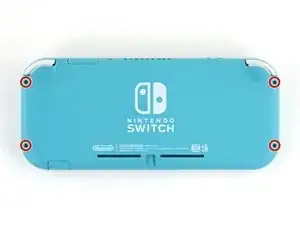
Usa un cacciavite tri-wing Y00 per rimuovere le quattro viti lunghe 6,3 mm che fissano il pannello posteriore.
-
-
-
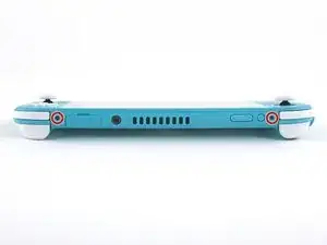
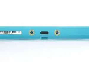
Usa un cacciavite a croce JIS o quello PH 000 ufficiale di iFixit per rimuovere le seguenti viti di fissaggio del pannello posteriore:
-
Due viti lunghe 3,6 mm nella parte superiore del dispositivo
-
Due viti lunghe 3,6 mm nella parte inferiore del dispositivo
-
-
-
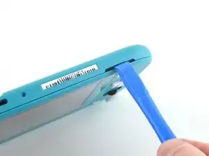
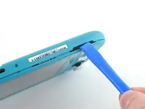
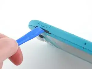
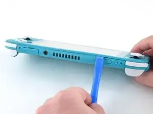
Inserisci uno strumento di apertura della griglia dell'altoparlante di sinistra, nella parte inferiore del dispositivo.
-
Torci lo strumento di apertura per sganciare le clip che bloccano il pannello posteriore.
-
-
-
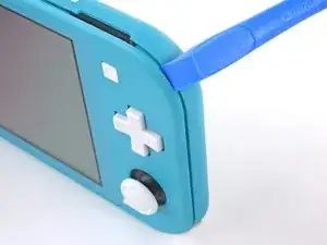
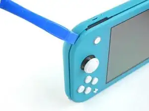
Fai scorrere l'attrezzo di apertura attorno al bordo inferiore sinistro per sganciare le clip sul lato sinistro del dispositivo.
-
-
-
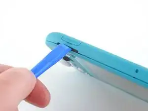
Inserisci uno strumento di apertura della griglia dell'altoparlante di sinistra, nella parte inferiore del dispositivo.
-
Torci l'attrezzo per sganciare le clip che bloccano il pannello posteriore.
-
-
-
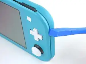
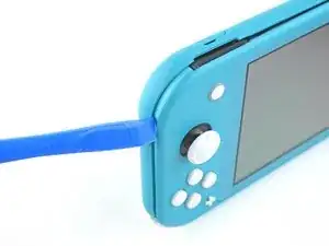
Fai scorrere lo strumento di apertura attorno all'angolo inferiore destro e usalo come leva per liberare le clip sul lato destro del dispositivo.
-
-
-
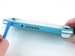
Continua a far scorrere lo strumento di apertura lungo la fessura fino alla parte superiore del dispositivo per sganciare le clip.
-
-
-
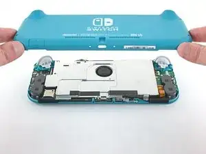
Solleva il bordo inferiore del pannello, aprendolo come un libro.
-
Rimuovi il pannello posteriore.
-
-
-
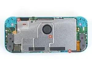
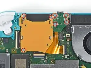
Usa un cacciavite a croce JIS 000 o quello PH 000 ufficiale di iFixit per rimuovere le seguenti quattro viti:
-
Tre viti lunghe 3,1 mm
-
Una vite lunga 4,5 mm
-
-
-
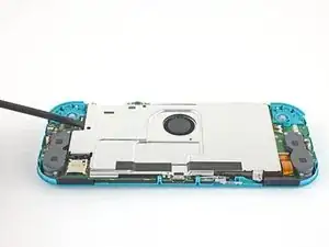
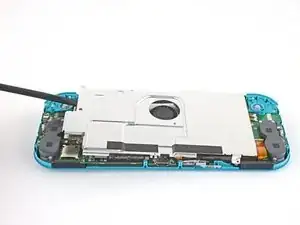
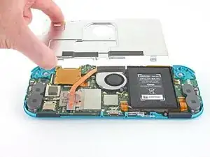
Usa uno spudger o le dita per sollevare la piastra di schermatura e staccarla dal dispositivo.
-
Rimuovi la piastra di schermatura.
-
-
-
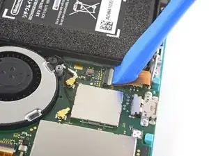
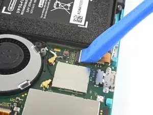
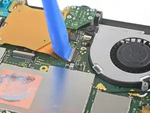
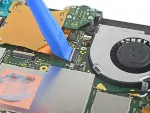
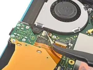
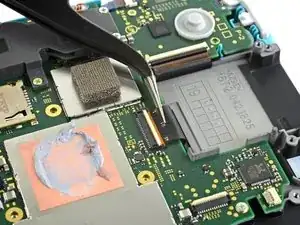
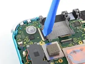
Usa uno strumento di apertura o un'unghia per ruotare la piccola aletta incernierata del connettore ZIF del cavo di interconnessione sulla scheda madre.
-
-
-
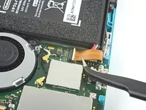
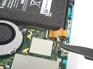
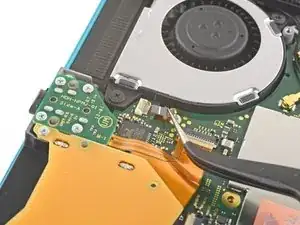
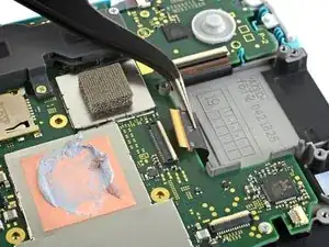
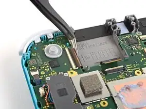
Usa delle pinzette per far scorrere fuori dal suo connettore e quindi scollegare il cavo di interconnessione sulla scheda madre.
-
-
-
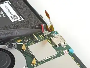
Usa l'estremità punta di uno spudger per sollevare il connettore della batteria estraendolo dal suo zoccolo sulla scheda madre.
-
-
-
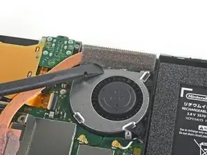
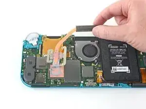
Usa la parte piatta di uno spudger per rimuovere delicatamente la schiuma adesiva sulla ventola.
-
-
-
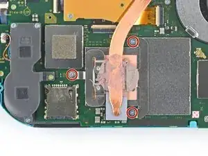
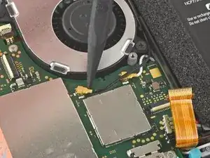
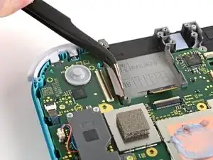
Usa un cacciavite a croce JIS 000 o quello PH 000 ufficiale di iFixit per svitare le tre viti da 3 mm che fissano il dissipatore alla scheda madre.
-
-
-
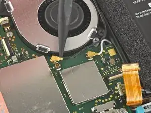
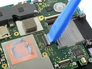
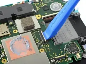
Usa un plettro o un'unghia per sganciare l'aletta di bloccaggio incernierata del connettore ZIF del cavo del lettore di schede.
-
-
-
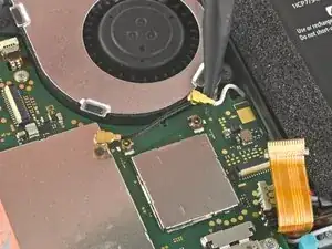
Usa un cacciavite a croce JIS 000 o quello PH 000 ufficiale di iFixit per svitare le sette viti da 3,1 mm che tengono ferma la scheda del jack audio e del lettore di schede di gioco.
-
-
-
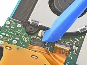
Usa le pinzette o le dita per sollevare la scheda del jack audio e del lettore di schede di gioco e spostarla a sinistra per sfilare il cavo dalla sua presa.
-
Rimuovi la scheda del jack audio e del lettore di schede di gioco.
-
-
-
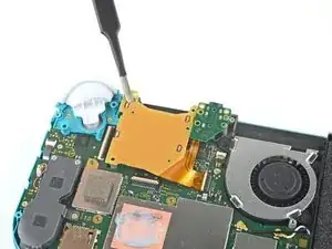
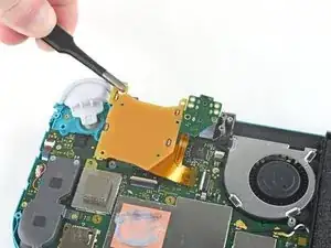
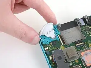
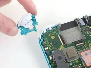
Usa un cacciavite a croce JIS 000 o quello PH 000 ufficiale di iFixit per svitare le due viti da 4,5 mm che fissano il gruppo del grilletto destro alla scheda madre.
-
-
-
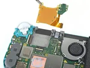
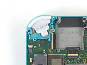
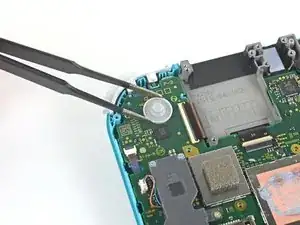
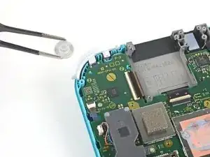
Usa un paio di pinzette o le dita per rimuovere la copertura in gomma del tasto del grilletto destro se non è rimasta attaccata al gruppo del grilletto.
-
-
-
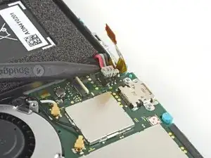
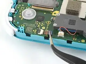
Usa la punta di uno spudger per far leva sul cavo nero dell'antenna e sollevarlo dalla sua presa sulla scheda madre
-
Ripeti la stessa procedura per il cavo di antenna bianco.
-
-
-
Usa un plettro o un'unghia per sganciare la piccola linguetta di bloccaggio incernierata del connettore ZIF della ventola.
-
-
-
Usa un paio di pinzette per sfilare il cavo dell'antenna dalla sua presa sulla scheda madre.
-
-
-
Usa un plettro o un'unghia per sganciare la piccola linguetta di bloccaggio incernierata del connettore ZIF del cavo dello schermo.
-
-
-
Usa un paio di pinzette per sfilare il cavo dello schermo dalla sua presa sulla scheda madre.
-
-
-
Usa un plettro o un'unghia per sganciare la piccola linguetta di bloccaggio incernierata del connettore ZIF del cavo del digitizer.
-
-
-
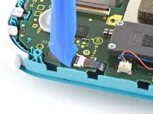
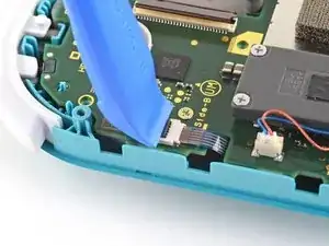
Usa un plettro o un'unghia per sganciare la piccola linguetta di bloccaggio incernierata del connettore ZIF del cavo del joystick destro.
-
-
-
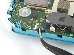
Usa delle pinzette per sfilare il cavo del joystick destro dalla sua presa sulla scheda madre.
-
-
-
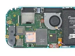
Usa un cacciavite a croce JIS 000 o quello PH 000 ufficiale di iFixit per svitare le seguenti sei viti che fissano la scheda madre:
-
Tre viti da 3,1 mm
-
Tre viti da 4,5 mm
-
-
-
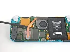
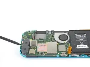
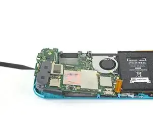
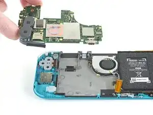
Infila uno spudger nella fessura tra la cornice e la scheda madre e solleva la scheda dal suo alloggio.
-
Rimuovi la scheda madre.
-
-
-
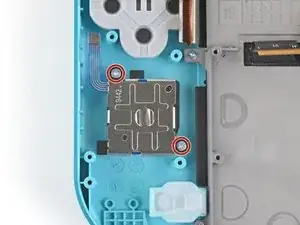
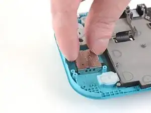
Usa un cacciavite a croce JIS 000 oppure un cacciavite PH 000 ufficiale di iFixit per svitare le due viti da 3,5 mm che fissano la levetta.
-


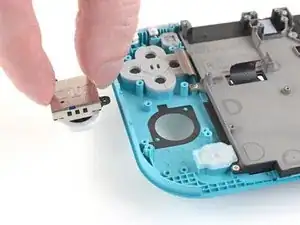
Per riassemblare il tuo dispositivo, segui questa guida al contrario.
Porta i tuoi rifiuti elettronici a un Riciclatore certificato R2 o e-Stewards.
La riparazione non è andata come previsto? Prova alcune soluzioni di base ai problemi o rivolgita alla nostra comunità Risposte Nintendo Switch Lite per trovare aiuto.

23 commenti
Not for the faint of heart and will take much longer than the indicated time. In the end bring it to a professional, as the battery does NOT come off as indicated. I now have an even more expensive repair as the battery socket came off the motherboard.
This is for a joy stick repair...
No Name -
This looked a bit daunting at first, but as you start going you get into a flow and as long as you follow the instructions slowly and carefully you shouldnt have a problem. I would say i finished in the recommended time.
Great guide - completed with no issues easily within the recommended time.
All my screws got stripped any ideas on how to remove?
Almost A Mammal -
A Y0 screwdriver seemed to work better for me.
Tommy Morrill -
What type of screw driver do I use to un screw the screws and which way
Luca Capito -
Y 0.6 was all I had but it seemed to fit perfectly
Trevor -