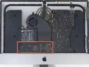
Introduzione

Usa questa guida per sostituire la scheda AirPort/Bluetooth.

  1. bKJMGPZdOUDLNefO
    • Con il cardine libero di muoversi, l'iMac sarà sbilanciato e la lavorazione risulterà difficoltosa. È possibile effettuare le riparazioni come indicato, ma risulteranno più semplici e veloci mediante il Cuneo Riparazioni Mac.

    • Se stai usando il supporto in cartone iFixit, segui queste istruzioni per montarlo.

    • Prima di iniziare a lavorare sull'iMac: Scollegare il computer dall'alimentazione e tenere premuto il pulsante di alimentazione per 10 secondi per scaricare i condensatori dell'alimentatore.

    • Fare molta attenzione a non toccare i contatti dei condensatori o qualsiasi punto di saldatura esposto sulla parte posteriore dell'alimentatore. Maneggiare la scheda tenendola solo dai bordi.

    I have (21.5 inch, mid 2017, 2.3 ghz) base model same as this but not 4k. How much max ram can I install in my iMac??

    Narendra Verma -

    This guide contains many extra steps for what should be a straight forward, simple parts replacement without disturbing more than the display, left hand speaker and removal of 4 logic board screws for play. Nothing else except for the left hand speaker wire & iSight cable from logic board, the lower support bracket and loosening the speaker so as to move it around a bit.

    For the ram, I bent a pair of cheap tweezers long ago supplied with these replacement kits to the perfect angle for holding, locating and inserting the ram into the slots under the logic bd after moving each retainer w/spudger and popping out the old. Pay attention to the orientation of the ram when removing/inserting the ram! An automotive mirror is handy along with a small flashlight for closeups. Once the ram is aligned properly substitute your fingers for the tweezers, ease it into the slot, push up & engage! Reinstall screws and all else. I have done this job successfully this way countless times. For a tweezers pic contact me!

    Ross Elkins -

    Additionally, if a blade is present, I install the OSx system on the blade and everything else, apps and home folders on the new SSD. You get the very fast boot off of the blade and the full ssd for all else!

    Ross Elkins -

  2. lLXyIR2flmAoZYtJ
    lLXyIR2flmAoZYtJ
    1VjZxwDRxkZGHBei
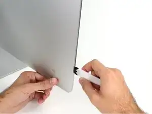
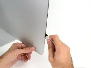
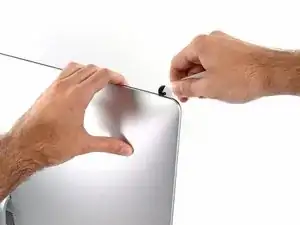
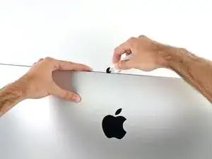
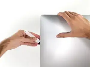
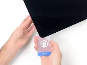
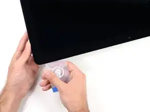
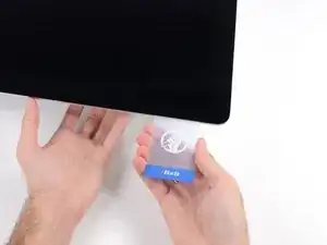
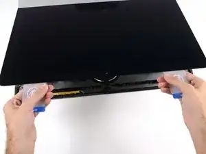
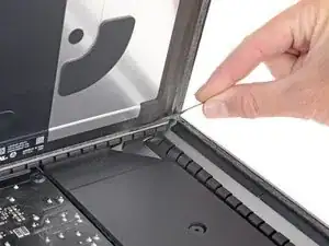
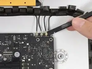
    • Iniziando sulla parte sinistra del display, accanto al pulsante di alimentazione, inserire l'attrezzo per l'apertura dell'iMac nello spazio fra il pannello di vetro e il case posteriore.

    • Il perno sull'attrezzo per l'apertura dell'iMac impedisce di inserire la ruota troppo a fondo. Nel caso di utilizzo di un altro attrezzo, non inserirlo nel display per più di 9,5 mm, poiché si rischia di tranciare i cavi dell'antenna e provocare danni gravi.

    • Sii delicato! Il vetro può rompersi se lo forzi troppo. Usa un asciugacapelli per scaldare i bordi e ammorbidire il nastro se la temperatura ambiente è bassa.

    Always use a hairdryer!! I cracked my glass

    8bit !!! -

  3. q3DRspiqEjuFxgCN
    q3DRspiqEjuFxgCN
    iCIN52QoBl3OSb6Z
    XxXjXdcFgFKcwebo
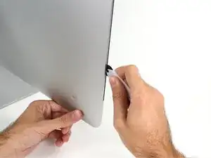
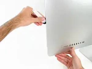
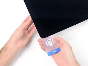
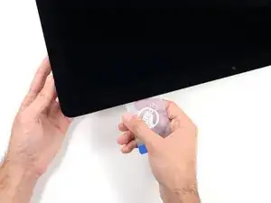
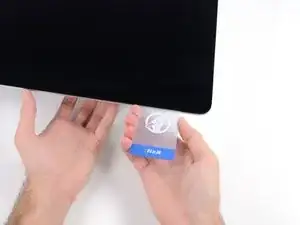
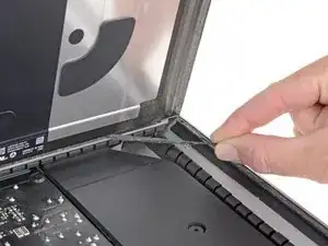
    • Utilizza l'attrezzo come una rotella tagliapizza: fallo scorrere nella feritoia e taglierà a metà le strisce adesive in schiuma.

    • Assicurati di usare l'impugnatura in modo che la rotella venga sempre spinta in avanti. Se la rotella viene tirata, può staccarsi dall'impugnatura

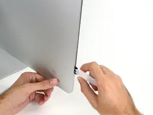
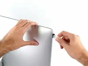
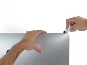
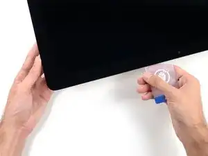
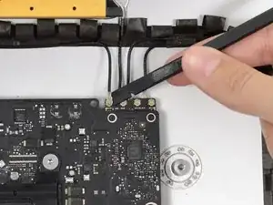
    • Usa l'attrezzo lungo il lato sinistro del display.

  4. vxDgcmqUtQlSsP2J
    vxDgcmqUtQlSsP2J
    DclVW5XnhQLHXKLH
    yEeTWsNVKZWwY4wC
    • Continuare a far scorrere l'attrezzo attorno all'angolo superiore sinistro.

  5. IGjiVeV2qMlPFjxo
    IGjiVeV2qMlPFjxo
    q2QGyKWGiqL4KJI1
    • Tagliare l'adesivo lungo il lato sinistro del display.

  6. XADEwykRUWgZNaKi
    XADEwykRUWgZNaKi
    Gy2L2NEQNABHTJKk
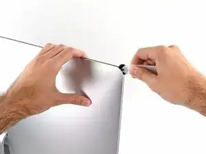
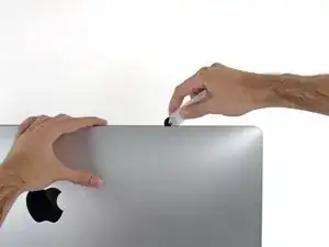
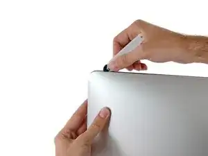
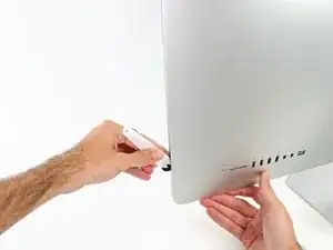
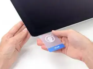
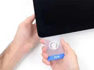
    • Continuare lungo la parte superiore del display.

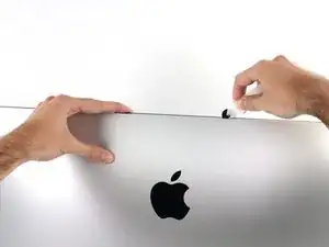
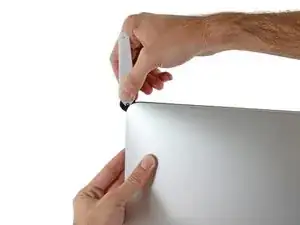
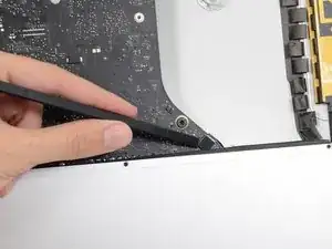
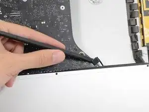
    • È consigliabile far scorrere ripetutamente l'attrezzo avanti e indietro lungo la parte già tagliata, per fare in modo di separare il più possibile l'adesivo.

  7. VIOSQOTIDCMkBXCd
    VIOSQOTIDCMkBXCd
    G6WL6LwKnmU4iroY
    QYGjK5rCFLbXb3Qg
    • Premere l'attrezzo attorno all'angolo superiore destro del display.

  8. sbN34h2LCe1hAMgV
    sbN34h2LCe1hAMgV
    4jyREp3qpSKjKIIg
    • Far scorrere l'attrezzo verso il basso, lungo il lato destro del display.

  9. sTI1wGwtH1grQmgO
    sTI1wGwtH1grQmgO
    HS5XEQmVYcECrOaG
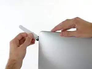
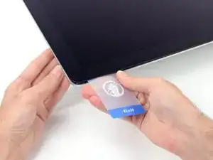
    • Terminare l'applicazione dell'attrezzo per l'apertura nella parte inferiore del lato destro del display.

    • A questo punto, si consiglia di ripassare nuovamente l'attrezzo lungo tutto il display, per fare in modo di tagliare il più possibile l'adesivo.

  10. RTJ4GtGmMD5uIEJh
    RTJ4GtGmMD5uIEJh
    kt1O3uj3QfiSMPoV
    3LsFsjkUGlXdNkXp
    • Sebbene l'attrezzo per l'apertura consenta di completare gran parte dell'operazione, il display sarà ancora leggermente attaccato al case. Occorre una scheda di plastica per liberare la parte restante dell'adesivo.

    • Poggiare l'iMac su un tavolo, rivolto verso l'alto.

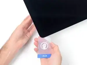
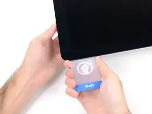
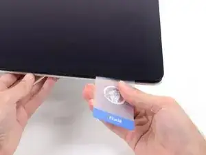
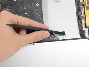
    • A partire dall'angolo superiore destro dell'iMac, inserire una scheda di plastica fra il display e il telaio.

    • Fare attenzione a non inserirla per più di 0,95 cm, in caso contrario si rischia di danneggiare i componenti interni.

    Don't forget to place the mac face up on the table. Unlike older models, there is no more flap at the bottom holding the display in place. If you do these steps with the Mac upright, the screen will pop out, hit your table, and shatter :( Don't ask me how I know.

    John M -

    So sorry. Thanks for that caution.

    Ted Horodynsky -

    Using suction cups (the ones that were made for removing the magnetic front glass on the 2011 and earlier iMacs) work well too. Place one in each top corner, while the Mac is lying face up on a table, and gently pull and it will separate the display from the main body. You might need to do a little more slicing around the edges if you did not get all the way through the first time with the roller. Then you can lift the display up at an angle to disconnect the cables.

    Peter Hillman -

    This was a great idea, worked well for me. Thanks!

    Florin -

  11. CAOhMNI4p5JGUSxH
    CAOhMNI4p5JGUSxH
    DcZsndbhPJvQEXcN
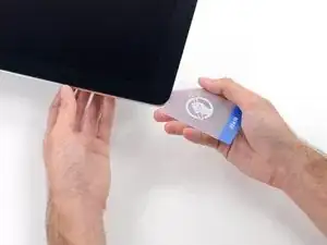
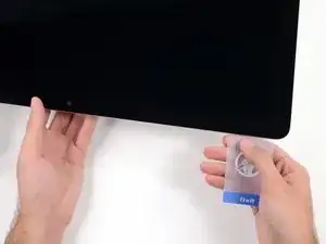
    • Ruotare delicatamente la scheda di plastica per aumentare lo spazio fra il display e il telaio.

    • Eseguire movimenti lenti, facendo attenzione a non fare troppa pressione sul vetro del display, poiché occorre solo uno spazio di circa 0,63 cm.

  12. 2i6VCJEZEQJjRAe4
    2i6VCJEZEQJjRAe4
    EKq3qJ4K11BdEByb
    T3tacDNMqHrTGNWg
    • Far scorrere la scheda verso il centro del display, per tagliare il resto dell'adesivo.

    • Occorre fermarsi prima della fotocamera iSight per non danneggiarla.

  13. wQERHWdpfWs1XOgE
    wQERHWdpfWs1XOgE
    5UWkeELY6pQH3NFW
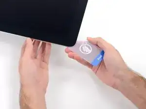
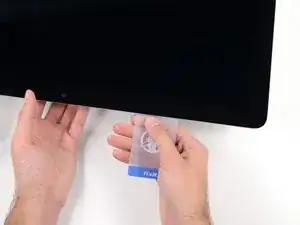
    • Inserire nuovamente la scheda nell'angolo e lasciarla in sede per evitare che l'adesivo si riattacchi.

  14. EZXvkfwJOBpSYIGk
    EZXvkfwJOBpSYIGk
    GSZKR1lbwrWhLwOU
    dOKjiA5VvyekxdI2
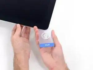
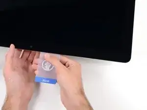
    • Inserire una seconda scheda nello spazio fra il display e il telaio nell'angolo superiore sinistro.

  15. qX1qFvFNr6TFKwG4
    qX1qFvFNr6TFKwG4
    FXVtoJOGxtCAlVoQ
    • Ruotare delicatamente la scheda per aumentare leggermente lo spazio fra il display e il telaio.

    • Come sulla parte opposta, spostarsi lentamente per consentire la separazione dell'adesivo, senza esercitare una pressione eccessiva sul vetro del display.

  16. c6X1bJH5UoyVj3JX
    c6X1bJH5UoyVj3JX
    LoDCrDsP2qvnxNSA
    iI6qGV3hZ5mfJmfY
    • Far scorrere la scheda di plastica verso il centro, fermandosi nuovamente prima della fotocamera iSight.

  17. NtIc2CuYM4tYdfVl
    NtIc2CuYM4tYdfVl
    DYKiZ46YtHUNBJpB
    • Reinserire la scheda nell'angolo superiore sinistro.

  18. mabnnjap5BGBwNCw
    mabnnjap5BGBwNCw
    2iYBEleZtKBCSqD4
    I2ivlTNZbwtjcNNT
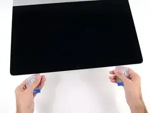
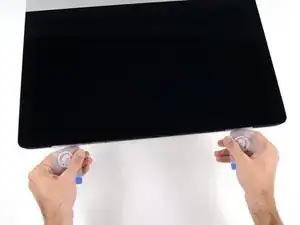
    • Mantenendo le schede inserite vicino agli angoli come indicato, ruotarle delicatamente per aumentare lo spazio fra il display e il case.

    • In presenza di sezioni ancora incollate che non si separano, fermare la rotazione e utilizzare una delle schede per tagliare l'adesivo nel punto interessato.

    • Iniziare a sollevare la parte superiore del display dal telaio.

    • Sollevare lo schermo di pochi centimetri, poiché è ancora collegato all'iMac mediante i cavi di alimentazione e dei dati.

    Ne forcez surtout pas et soulevez l’écran par les deux extrémités ! Il faut que tous les adhésifs soient bien découpés pour que l’écran se dégage du boitier sans effort. Toute torsion de l’écran peut entraîner une superbe fissure sur le verre :-/

    mf -

  19. Lq3NWNyJjC6ivpoe
    Lq3NWNyJjC6ivpoe
    YW6sgdgvnCF2BTt6
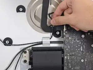
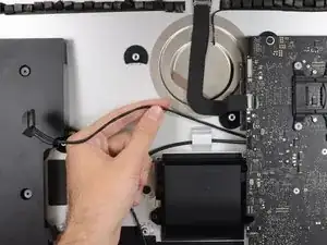
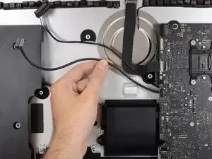
    • Mantenendo sollevato il display con una mano, utilizzare l'altra per scollegare il cavo di alimentazione.

    • Sollevare il display per avere sufficiente spazio per accedere alle connessioni, ma senza tirare i cavi né sollecitare eccessivamente i connettori (circa 20,32 cm).

    As seen in photo:

    bottom cable pulls up

    top cable cable pulls right, after safety clip opened

    airshack -

  20. PDABAgqTKP5Sfm6D
    PDABAgqTKP5Sfm6D
    R6ouHGmTXkOGDImj
    LntmZHgb1OOmYq3s
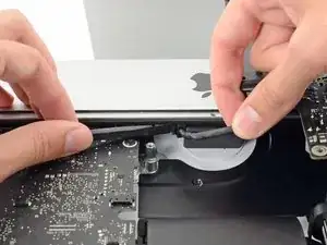
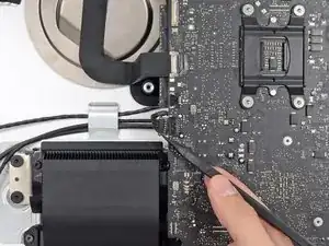
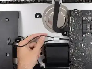
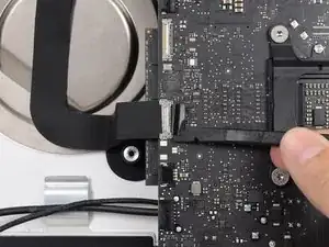
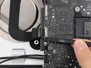
    • Ruotare verso l'alto la staffa metallica di fissaggio sul cavo dati del display.

    • Scollegare il cavo dati del display.

    • Si tratta di una connessione delicata che può danneggiarsi facilmente. Estrarre completamente il cavo dati del display dal relativo connettore, verso la parte superiore dell'iMac.

  21. 22yPwf2Vt6ac6vgN
    22yPwf2Vt6ac6vgN
    hiCUZB1J4KJDVbed
    • Sollevare il display in posizione semi-verticale.

    • A questo punto, sarà ancora presente una striscia di adesivo lungo la parte inferiore del display, che lo terrà bloccato al telaio come un cardine. È possibile allentare l'adesivo muovendo ripetutamente il display verso l'alto e verso il basso.

    There are pull tabs at each side off the bottom edge to allow easy release of the tape

    DarrenG -

    DarrenG’s observation about the pull tabs saved me a ton of time trying to pry the display as per the original instructions. Thanks!

    lesfam5 -

  22. 6A4EHvapeoMdolHS
    6A4EHvapeoMdolHS
    U2m5h1GFWVElYlqZ
    MbYvBcby3LvdmdUa
    • Stai molto attento a non toccare i contatti dei condensatori o qualsiasi saldatura esposta sul retro dell'alimentatore (evidenziato in rosso).

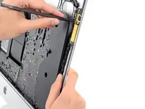
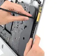
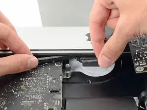
    • Prendi la piccola aletta all'estremità di una delle strisce adesive ai bordi inferiori dello schermo e tirale verso la parte superiore dell'iMac per rimuoverla.

    • Ripeti questo passaggio con l'altra striscia adesiva e rimuovila.

    • Se una delle strisce adesive si rompe prima di averla rimossa, usa una scheda in plastica per tagliare l'adesivo rimasto.

    The roller tool for slicing open the display works great for this step. Get in there like using the card and roll across the bottom to slice through the remaining adhesive.

    Peter Hillman -

  23. NZoUcXcRjHHrjqib
    NZoUcXcRjHHrjqib
    GyD3PrjUqBoNiCEp
    lU5PpvNXQBkB1Oyk
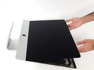
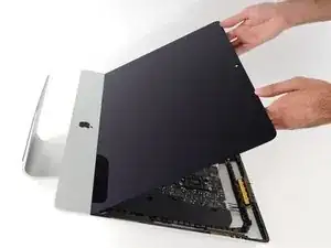
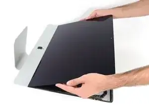
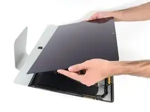
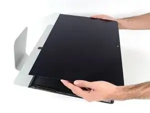
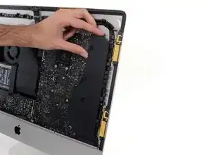
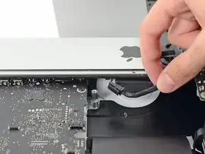
    • Solleva il display dal telaio e rimuoverlo dall'iMac.

    • Potrebbe essere necessario sollevarlo lentamente da un lato per liberarlo dall'adesivo restante.

    • Maneggia il display con attenzione poiché è ingombrante, pesante e fatto di vetro.

    • Durante il riassemblaggio, rimuovi tutte le tracce dei vecchi adesivi dall'iMac, quindi prima di reinstallare lo schermo guarda la nostra guida alla sostituzione delle strisce Adesive per l'iMac Intel Retina Display 4K (2017) 21,5" (EMC 2544).

    After removing the display, I also removed the 3 screws for the processor fan, disconnected the power connector for it and set the fan shroud aside. Disconnecting the remaining cable (similar style to 1 of the cables for the display) that is in the way of the RAM chips is all that's left to do. I was then able to access and quickly remove the two Apple-provided RAM chips, and replace them with 3rd party RAM. Turning the iMac on its side, so that it's in a position where you're physically putting the RAM chips DOWNWARD into their respective slots is the best way to go about uninstalling and reinstalling the chips. Using a narrow but long'ish plastic spudger tool is the best way to defeat the spring-tabs which hold the RAM chips in place. After removing the LCD display, changing the RAM is about a 10 minute process!! And I'd SURE prefer not to remove all the parts and risk damage to the iMac via the standard procedure listed. As per usual, take your time and work gently :-)

    Mitch K -

    Teardown the whole machine just to change RAM? While preparing to comment on this procedure I just noticed the comment made by Mitch K above. I ran pretty much the same procedure that he describes this afternoon (steps 1-23, 43-45, and step 55). Then I swapped out the original 2x4GB RAM chips for 2x8GB chips by reaching behind the logic board, releasing the spring retaining clips one chip at a time (starting with the chip further away from the logic board), pivoting the RAM towards the back of the machine, and then carefully sliding it out of the slot. I easily slid in the new chips and then pivoted them to lock them down. No hassle, no time lost. As Mitch K states above, not only is this “shortcut” method much quicker and easier, but it provides less risk of damaging cables, sockets and other delicate components during a total teardown. Why mess with the power supply board just to change RAM? I do not advise to follow the current iFixit.com procedure written by Sam Lionheart, regardless of user skill-level.

    nycsandor -

    THAT sounds one !&&* of a lot easier than the full tear down. I wonder if there’s a video of the process described by Mitch K? Adding that to these verbal instructions would really help relieve the apprehension and anxiety around the process! I do sometimes find the additional warnings, though appreciated from a “safety first” perspective, are somewhat overstated. It’s been a very long time since I shorted out RAM, or fried a PCB, or broke a connector, regardless of how finicky, fragile or awkwardly designed and positioned. I may have WANTED to break something, and the air might be blue for a few seconds, but inevitably, things go back together, the start button gets pressed, the startup chime sounds, and we’re in business. Practice DOES make as close to perfect we are likely to get.

    bruce -

    Mitch has the exact method that works a treat. You don’t need to follow steps 24-37 and also 40-63. Step 51 is the step to remove the camera cable and is needed. Steps 38 and 39 are for the Fan. That is all that is needed. Done quite a few like this.

    Be careful not to drop the RAM down the back of the logic board!

    By NOT removing all the other stuff you can avoid either damaging it or forgetting to plug in a cable.

    Charlie Nancarrow -

    I just trued this shortcut and it was not successful. I was not able to seat both RAM chips with this shortcut, and managed to slightly damage one of the retainer clips. I simply could not manipulate the chips into and out of the slots effectively without taking everything apart as described in the full set of steps.. I ended up retracing my steps and following the entire procedure, carefully, and that worked without incident. So, bottomline, it is definitely more work to follow all the steps but from my experience, it is decidedly safer. Your mileage may, of course, vary. It was successful in the end, and I swapped out the hard drive with an ssd during the same procedure and my machine is very, very much faster.

    jan -

    I have completed by following the Mitch K post and it is much easier than stripping down the whole thing, just be aware that to remove and replace the ram chips means working in a tight space, you need slim fingers and don’t be tempted to use force, take your time.

    Barrie Price -

    Well, I have slim fingers, but they are 60 years old, and they don’t work like they used to! LOL.

    Jan Hogle -

    Agree with Mitch K’s procedure. The only added tip I would throw in is to use two 45 degree tweezers with their plastic covers still installed to easily pop loose the RAM. I couldn’t get the plastic spudger tool to work myself, but the tweezers easily reach the RAM clips. Just make sure the plastic covers are installed and you won’t be in danger of scratching or shorting anything out.

    charlesnick -

    So thankful I discovered these comments. Saved me a TON of time! Thank you!!

    Adam Roberts -

    These comments were very useful. Thank you. I just needed to modify a pair of tweezers to allow me to seat the new RAM more easily. The ifixit screwdriver wasn't able to turn some of the screws as they were installed too tightly, and I didn't want to wait to order and reveive a pair of right angled Torx screwdrivers that would give me more leverage to get those boards off.

    Upgrader -

  24. bpB3vigPkDEJaODx
    bpB3vigPkDEJaODx
    UHTtExuT2rlyLtDU
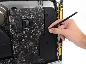
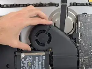
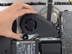
    • Usa uno spudger per rilasciare il connettore del cavo dello speaker destro dalla sua presa sulla scheda madre.

    • È utile spingere verso il basso su entrambi i lati del connettore per guidarlo fuori dalla sua presa. Stai attento ai bordi del connettore: si possono rompere facilmente.

    • Tira il connettore verso il basso per sfilarlo dalla sua presa.

    I highly recommend doing steps 27 and 28 first and then pull out the cable. It will give you more room on the right side of the cable to work with making this step that much easier.

    Eddie de la Rosa -

    The two corners of the connector are latches that need to be pushed toward the center of the connector to release. This is easily done with the pointed end of the spudger. Once the two corner latches are released, the connector comes apart easily.

    Fred Heineman -

  25. eCECFTFAxFIpXI2B
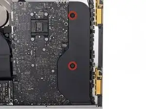
    • Svita le due viti Torx T10 da 10,0 mm che fissano lo speaker destro alla copertura posteriore.

  26. ZZqU2JxJYESWeUCM
    ZZqU2JxJYESWeUCM
    VVVam54h3KT1T4jP
    • Solleva di un paio di centimetri lo speaker destro dalla copertura posteriore, per scoprire il cavo dell'antenna che passa sul suo bordo destro.

  27. 6QcZ5VEKCJgmeRCT
    6QcZ5VEKCJgmeRCT
    ZaV2LVgFyHTlDiiE
    5EQPXsfOcYVgq1pW
    • Infila la punta di uno spudger tra lo speaker destro e il cavo dell'antenna che è infilato nel bordo destro dello speaker.

    • Fai scorrere lo spudger lungo il bordo destro dello speaker per separare il cavo dell'antenna dal suo alloggio nello speaker destro.

  28. SUeeAI2YcIEFbu5C
    SUeeAI2YcIEFbu5C
    EIiSYybDS5fUSvRq
    VTDXemYXPxyIVaBw
    • Tira lo speaker destro verso l'alto per un paio di centimetri, verso la parte superiore dell'iMac.

    • Tira lo speaker verso l'alto e rimuovilo dall'iMac. Questo passaggio può richiedere della forza: usa entrambe le mani e fai ondeggiare lo speaker avanti e indietro lo speaker per rimuoverlo.

    Th HP is VERY HARD to take off in this thin place

    bruno -

  29. eJkD4BRQM4pFSEkg
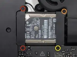
    • Rimuovi le seguenti viti che mantengono al loro posto le staffe di bloccaggio che fissano il disco rigido alla scocca posteriore:

    • Due viti Torx T10 da 21 mm sulla parte sinistra della staffa del disco rigido.

    • Una vite Torx T10 da 9 mm.

    • Una vite Torx T10 da 27 mm.

    Pay attention to this photo and where the fan is. It is 180° from where the previous step shows it is oriented to you.

    Max Romano -

  30. jjmgaJBQQ3GCBXAJ
    jjmgaJBQQ3GCBXAJ
    OYaQKvCeXcNJ5pXZ
    • Rimuovi dal tuo iMac le staffe di bloccaggio destra e sinistra dell'hard drive.

  31. ZUXdAYsboViNN3LP
    ZUXdAYsboViNN3LP
    2B4ULK3qyBRHyCjA
    rjaYEgxfA6XedhVp
    • I prossimi passi ti porteranno a lavorare vicino alla faccia esposta dell'alimentatore. Non toccare la faccia dell'alimentatore per evitare una scossa ad alta tensione dei diversi grandi condensatori saldati alla scheda.

    • Usa la punta di uno spudger per spingere entrambi i lati del connettore del cavo del tasto di accensione e guidalo delicatamente fuori dalla sua presa.

    Accomplished with spudger on top and thumbnail on bottom. Otherwise couldn’t rock it loose.

    airshack -

  32. nDL1ZXuaLdV51GA5
    nDL1ZXuaLdV51GA5
    6hAjlFateirPRtNq
    • Spingi delicatamente verso l'alto su entrambi i lati del connettore del cavo del controllo dell'alimentatore con la punta di uno spudger per guidarlo delicatamente fuori dalla sua presa.

    Doing this with spudger on right and thumbnail on left seemed easier and safer.

    airshack -

  33. 6SRtDZMjfIshtcEC
    • Svita le due viti Torx T10 da 7,2 mm che fissano l'alimentatore alla copertura posteriore.

    What if these are too tight to remove?

    Rafael Garcia -

    Hi Rafael,

    Be very careful not to strip these screws. Use a new, accurate T10 bit and a driver with good leverage to loosen these screws.

    Arthur Shi -

    They are T9 in my iMac

    Glenn Koslowsky -

    They were T8 screws on my machine.

    Ed Beachwood -

  34. DZGfKeTNNZRF5rIY
    DZGfKeTNNZRF5rIY
    XZToZZtKeCxR24Or
    • Mentre lavori sull'alimentatore, stai molto attento a non toccare i contatti dei condensatori o qualsiasi saldatura esposta sul retro dell'alimentatore. Tieni la scheda solo dai bordi.

    • Inclina in avanti l'alimentatore.

  35. PnVpN4P5Q41LIcjX
    PnVpN4P5Q41LIcjX
    KYXTDvFWXOOKGo4w
    KotmGxZn3Tbp5oDl
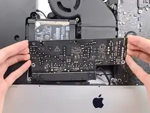
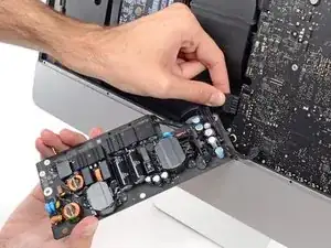
    • Tira leggermente l'alimentatore verso l'alto e fuori dalla copertura posteriore.

    • Ruota l'alimentatore in senso antiorario, sollevando il bordo destro di un paio di centimetri più un alto del sinistro.

  36. dWkMC3KPAiJZ2BYA
    dWkMC3KPAiJZ2BYA
    VdKRfPUme1WjaaxJ
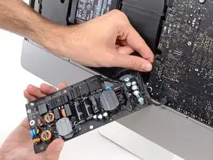
    • Sposta l'alimentatore verso destra per superare il supporto della vite sulla copertura posteriore.

  37. atXqqTlMIcRfaLqZ
    atXqqTlMIcRfaLqZ
    pCEqH332pgmfCpr1
    hgPesfBdCbjpNkCx
    • Fai ondeggiare l'alimentatore avanti e indietro e rimuovilo dal suo alloggio nella copertura posteriore.

    • Non cercare ancora di rimuovere del tutto l'alimentatore dall'iMac: è ancora collegato alla scheda madre.

  38. wNJxtUCC3jTRJDMO
    wNJxtUCC3jTRJDMO
    NQOgcUB1WXOVvdIi
    • Stai molto attento a non toccare i contatti dei condensatori o qualsiasi saldatura esposta sul retro dell'alimentatore. Tieni la scheda solo dai bordi.

    • Gira la parte superiore dell'alimentatore verso di te per accedere al connettore del cavo di alimentazione DC dietro la scheda madre.

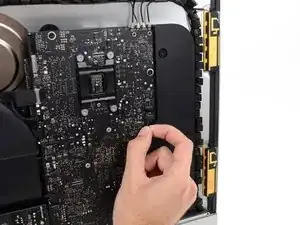
    • Schiaccia l'aletta su connettore del cavo di alimentazione DC sfilalo dalla sua presa sul retro della scheda madre.

    what happens if you damage the power socket on the logic board?

    Racheal Major -

    The tab is on the bottom of the connector. You can’t see it. Squeeze the bottom of the connector close to the cables to properly release tab. Pulling straight out is important.

    Eddie de la Rosa -

    This step might be easier if you do the next step first (step 41) and then come back to this step.

    Eddie de la Rosa -

    I loosened the logic board attached to the power supply board. I then could easily remove the 2 power cables.

    Gerard Stoffels -

    A photo of the disconnected power connector would be helpful in seeing how the tab release works here.

    airshack -

    In the photo above, the index finger is shown squeezing the connector locking tab. Do this while using the flat end of a spudger to release the latch. Once the connector is moved about an eigth of an inch the latch is released and the connector should come out freely.

    Fred Heineman -

    The photo you added is of the wrong side of the power cable connector? Please add a photo of the rear facing side so the clip mechanism so disconnection can be clearly understood.

    airshack -

    The key is to squeeze the tab in the part near the cables. You won’t feel like the tab is moving, but squeezing it there is necessary to get it out.

    Adrià -

  39. EyLJWWk2OFr5HCye
    EyLJWWk2OFr5HCye
    AlMArQO33R1TWQ6T
    DMjNbUXoMgsocggq
    • Potresti trovare utile stendere l'iMac sul tavolo per i prossimi passaggi.

    • Usa la parte piatta di uno spudger per spingere il gancio sul lato del connettore del cavi di ingresso AC verso l'interno.

    • Mentre tieni il gancio di rilascio con lo spudger, prendi il cavo di ingresso AC e tiralo per sfilarlo dalla sua presa.

  40. WBIpQxLH3fEByo23
    • Rimuovi l'alimentatore dall'iMac.

  41. KceINyPjQiQDjfoZ
    KceINyPjQiQDjfoZ
    ngKJySbkFQwLlq6w
    • Tira delicatamente il connettore del cavo della ventola per sfilarlo dalla sua presa sulla scheda madre.

    I don’t like to pull on wires as shown in the photos above. I used my index fingernail on the top corner of the connector and the pointed end of a spudger on the bottom corner to pull the connector straight out of its socket.

    Fred Heineman -

  42. 1PLJEbleesQUVGR3
    • Svita le tre viti a colletto Torx T10 che fissano la ventola alla copertura posteriore.

  43. 4tLv2VGQeJSNgTP1
    4tLv2VGQeJSNgTP1
    vNhgCQACpS5UShZl
    • Rimuovi la ventola dall'iMac.

  44. 36DsTBiHTPsP5aVU
    36DsTBiHTPsP5aVU
    gTU24uLBYOIv4Mhy
    KNinFGbODGTjoQq1
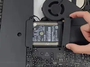
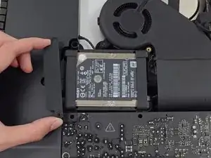
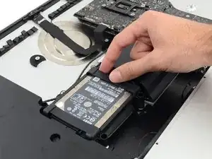
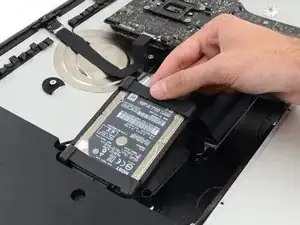
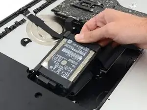
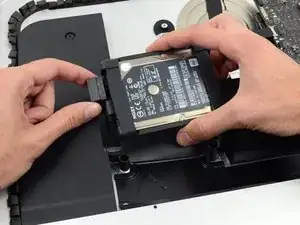
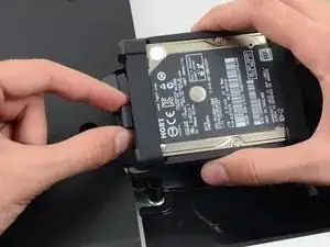
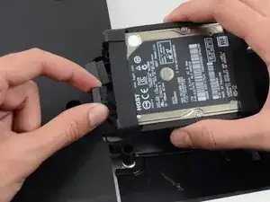
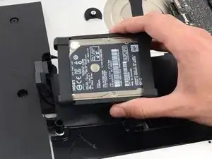
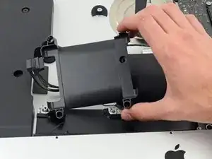
    • Solleva l'hard drive dal bordo più vicino alla scheda logica ed estrailo leggermente dalla sua sede.

    • L'hard drive è collegato tramite due cavi, non tentare di rimuoverlo completamente dall'iMac.

  45. ZxnqxTBEoc4w2LRN
    ZxnqxTBEoc4w2LRN
    ZlayYFLKmfxikbiA
    • Scollega il cavo di alimentazione SATA.

  46. W1BnV1ZiStMgG441
    W1BnV1ZiStMgG441
    QSE3SSpfyUcdRarK
    • Scollega il cavo dati SATA dal disco rigido.

  47. JCpSSKHxwDXCIdI2
    • Rimuovi il disco rigido dall'iMac.

  48. KhMofSoJJlhXl1jA
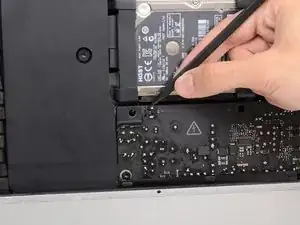
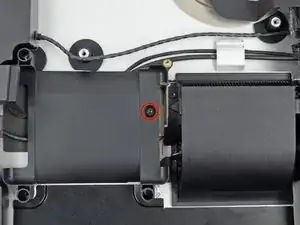
    • Svita la vite Torx T10 da 7,2 mm che fissa il carrello del disco rigido alla copertura posteriore.

    2017 imac EMC 3069 this is a T9

    Glenn Koslowsky -

  49. NwKSthHKJNo4gHC3
    • Rimuovi il carrello del disco rigido dalla copertura posteriore.

    Cables are routed through the backside of the tray. Take a picture for reassembly.

    Mitchell Scheffler -

  50. bpUJduIptxtCQTrJ
    bpUJduIptxtCQTrJ
    NY3U2MjTCPHSNjfv
    • Premi entrambi i lati del connettore del cavo dello speaker sinistro con la punta di uno spudger e guidalo delicatamente fuori dalla sua presa.

    As noted in the right speaker cable section, the two corners of the connector are latches that need to be pushed toward the center of the connector to release. This is easily done with the pointed end of the spudger. Once the two corner latches are released, the connector comes apart easily.

    Fred Heineman -

  51. nIBOyJbEX5Sl4Or2
    nIBOyJbEX5Sl4Or2
    pAPeO3l2vihSiYDM
    • Sfila il cavo dello speaker sinistro tirandolo verso l'alto, fuori dal gancio di bloccaggio sul retro della copertura posteriore.

  52. aPduYkOrm1ijEuIm
    aPduYkOrm1ijEuIm
    J3l5W2gyvQbjlT4W
    nPMIkqvYZHIUCEXb
    • In modo simile al passo precedente, sfila i cavi dati e alimentazione SATA dal gancio di bloccaggio.

  53. Oi1uPFeAgU4d4B1V
    Oi1uPFeAgU4d4B1V
    UQYT31FILKH2XlFo
    deVi3sgpTG6ko3ev
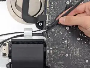
    • Usa la parte piatta di uno spudger per ruotare verso l'alto la staffa di bloccaggio in metallo sul connettore del cavo della fotocamera iSight.

    • Sfila il cavo della fotocamera iSight dalla sua presa sulla scheda madre.

    • Questo è un connettore delicato che può venire danneggiato facilmente.

    As seen in the photo this clip clearly has a pull tab. Forget the spudger and just open the clip with the pull tab.

    airshack -

  54. ChWlT2nybGpoDtrw
    ChWlT2nybGpoDtrw
    2LQdOvIdwuPacACY
    52lBdh3y1pIxgFri
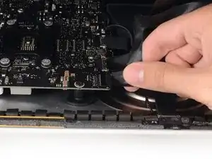
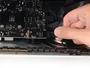
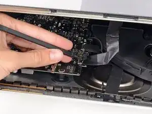
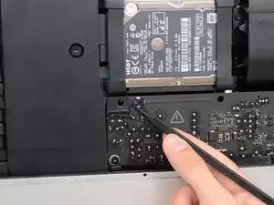
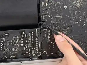
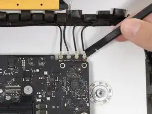
    • Usa la parte piatta di uno spudger per scollegare tutti i quattro connettori dell'antenna dalla scheda AirPort/Bluetooth.

    • Segna la posizione originale di ogni connettore per quando li dovrai ricollegare.

    I broke off one of the antenna connectors when I took off the antenna wires, but the new 802.11ac card is working:) I seems the way to take off the wires is lifting it up from the wire side. In hindsight I just wasn´t careful enough.

    Runar Vaernes -

    how do I check a working logic board

    Navneet Garg -

    I labeled mine with label printer labels prior to disconnection.

    airshack -

    I labeled mine with label printer labels prior to disconnection. The label/tabs made reinstalling easier as I held onto the label/tabs while pressing down on the connectors. Much easier than holding onto the physical wires.

    airshack -

    If you have a pair of angled tweezers, they work well for grabbing under the connector so that you aren’t pulling on the wire. The head of the T10 screwdriver works well for pressing them back on.

    Mitchell Scheffler -

    iMac 2017 EMC 3069 this has the antenna brackets with two T5

    Glenn Koslowsky -

  55. PVF2eFHOcWUlH6ov
    PVF2eFHOcWUlH6ov
    qbxXCqIthxynZ525
    tjH4h6FyAyucQGqX
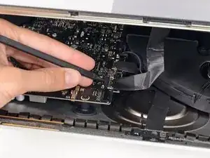
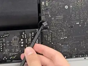
    • Usa la parte piatta di uno spudger per scollegare il connettore del cavo della presa jack dalla sua presa sulla scheda madre.

    • Spingi leggermente il cavo verso destra.

    Unlike the rest of the connectors on the logic board, this one lifts up away from the board rather than to the side. That “Push the cable slightly to the right.” notation is after the connector is free.

    Fred Heineman -

  56. QJIoRvsnlHELAikU
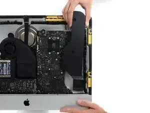
    • Svita le seguenti viti che fissano il condotto di scarico alla copertura posteriore:

    • Due viti Torx T8 da 6,3 mm

    • Due viti Torx T8 da 4,7 mm

    Weirdly, these screws didn’t work with my T8 driver. Not with T6 or T10.

    Every other screw (to this point) has been fine. Hmm.

    Jake Lodwick -

    ??? The T8 worked fine for me. Not sure what the difference would be.

    Fred Heineman -

    Fare molta attenzione alla vite in fondo a destra, è facile (soprattutto se la punta del proprio cacciavite non è magnetizzata) che la vite si perda sotto alla Logic board. Se la punta del cacciavite non è magnetizzata consiglio o di utilizzare un magnete esterno o di utilizzare delle pinze mentre si svita la vite in modo da non incorrere in questo problema.

    Carlo Molta -

  57. vTFjxoQJVL1LjsGU
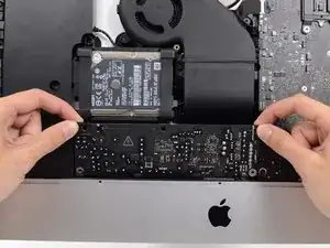
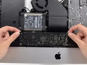
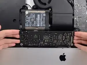
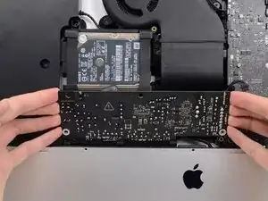
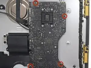
    • Svita le quattro viti Torx T10 da 7,2 mm che fissano la scheda madre alla copertura posteriore.

    When reinstalling the logic board, install four screws loose. Insert thumb drives into the back in all slots to ensure alignment. Once aligned, then tighten screws.

    Gary Kelch -

    On some models there is a tiny microphone cable connector, just above the lower left logic board screw. Remove by carefully pulling straight down. There is also a piece of insulating plastic w/adhesive on top of the screw which can be pulled off prior to removal. Save and reuse with the same screw on installation.

    Ed Beachwood -

  58. CbhcbTbVVbCDOdVR
    CbhcbTbVVbCDOdVR
    3ZWTvdymBERwUaSS
    kWgY5CCYya3SJRcj
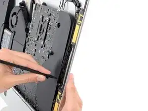
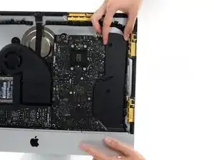
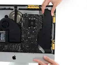
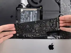
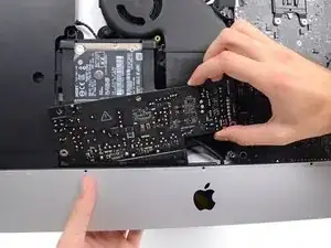
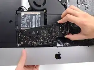
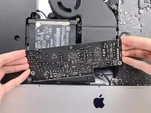
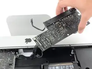
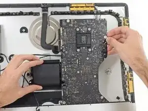
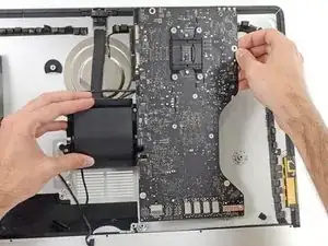
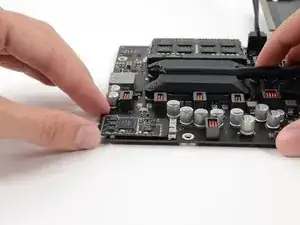
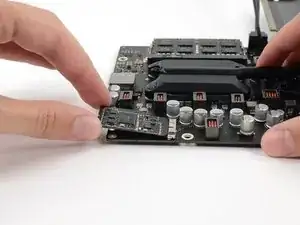
    • Allontana la parte superiore della scheda madre dalla copertura posteriore.

    • Solleva la scheda madre e rimuovila dall'iMac.

    • Stai attento a non far impigliare la scheda in nessun supporto delle viti della copertura posteriore.

    • Le schede I/O in fondo alla scheda madre saranno la parte più problematica. Ti consigliamo di tirare delicatamente per evitare danni.

    • Durante il rimontaggio della scheda madre, stai attento alla posizione dei connettori I/O. Dopo aver infilato la scheda nella copertura, inserisci una chiavetta USB o un cavo Thunderbolt in uno dei connettori per allinearla correttamente.

    When inserting the logic board back, pay attention of the position of the I/O connectors. When it is back in place, put a USB / Thunderbolt cable into the connectors to ensure the perfect alignment.

    Peter -

    This is fantastic advice. I used a combination of USB and display port plugs to ensure proper alignment and help keep the logic board steady while i screwed it back in. Thank you!!

    kazoodac -

    Great technique. I plugged a cable into every port before tightening logic board screws.

    airshack -

    ive gotten this far and i still have one question, i’m replacing my HDD With A SSD should i also remove the original Blade drive ? and run exclusively off the ssd, ? i wasn’t 100 on whether or not i was getting the fusion set up so i’m not in possession of a upgraded blade, so i though this was a good question id hadn’t seen asked.

    Eliasar -

  59. qcFs33lOLxZ1Ew5e
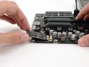
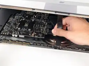
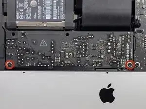
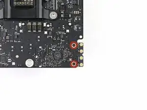
    • Rimuovi le due viti T5 da 3,2 mm che fissano la scheda AirPort/Bluetooth alla scheda logica.

  60. fUU53uiErRaC6ZEU
    fUU53uiErRaC6ZEU
    kTxSEMO11ibRrJYP
    WGyLCcwgXA2H1Abs
    • Solleva leggermente la scheda AirPort/Bluetooth e tirala fuori dalla sua presa.

    • Non usare troppa forza per tirare l'estremità della scheda fuori dalla sua presa o potresti danneggiare la presa.

    • Quando reinstalli la scheda, accertati che sia posizionata correttamente prima di reinstallare le viti di bloccaggio.

    I addition to the two Torx5 screws, My Wi Fi bluetooth card was glued to the main board with a grey porous glue that was easy to peel off once I got the card loose.

    Runar Vaernes -

Conclusione

Per rimontare il dispositivo, segui queste istruzioni in ordine inverso e usa la nostra guida per sostituire le strisce adesive per riattaccare il vetro del display.

Sam Goldheart

Membro da: 19/10/12

465140 Reputazione

3 commenti

I successfully upgraded the Wi-Fi Bluetooth card in my late 2012 iMac to 802.11ac following this guide! The new card is now the same as what´s in the new 2013 iMacs, I used the 2013 iMac teardown to find the right part:)

Runar Vaernes -

Do I need to remove/clean the paste that locks the card before installing a new one? If I use a used one, what kind of paste do I have to use to replace the old one?

Pzucchi -

I just bought a new BT card (a >2013 version!) and it works!!!! Just some advise before you start: follow the instructions above including step 28. At this point unscrew the big sized mainboard screws. This allows some movement so you can pull back the motherboard if needed and will avoid straining it to much. you can nog pull out the Bluetooth card without dismantling the whole computer! Putting the new card back also works fine this way. This Saves you massive time!

aarsentim -