
Introduzione
Segui questa guida per sostituire la scheda madre del Microsoft Surface Pro 4.
C'è una buona probabilità che tu rompa il pannello dello schermo non rinforzato e delicato durante questa procedura. Assicurati di scaldare a sufficienza ed essere molto attento mentre tagli l'adesivo. Indossa degli occhiali protettivi nel caso il vetro si rompa.
Applicare della nuova pasta termica durante il rimontaggio potrebbe migliorare le prestazioni del tuo Surface. Se vuoi farlo, assicurati di avere della nuova pasta termica e dell'alcool isopropilico ad alta concentrazione o un solvente specifico per la pasta termica.
-
-
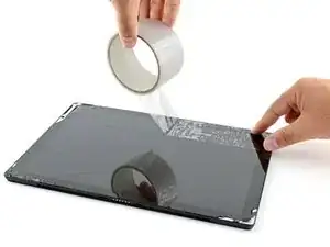
Se il tuo schermo è crepato, evita che si rompa ulteriormente e di farti male facendo aderire del nastro al vetro.
-
Fai aderire delle strisce di nastro adesivo trasparente che si sovrappongono sopra lo schermo del Surface fino a coprirlo del tutto.
-
Fai del tuo meglio per seguire il resto di questa procedura come descritta. Comunque, dopo che il vetro si è rotto, continuerà a creparsi mentre lavori e potresti dover usare uno strumento in metallo per rimuovere il vetro.
-
-
-
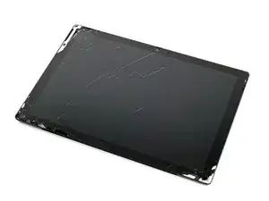
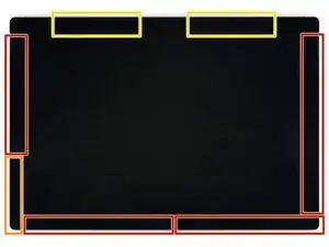
Prendi nota della disposizione dell'adesivo dello schermo prima di continuare:
-
Queste zone contengono solo dell'adesivo e puoi tagliare in sicurezza.
-
La scheda e i cavi a nastro dello schermo sono qui, vicino al bordo. Taglia con attenzione e non infilare il plettro per più di 3 mm.
-
I delicati cavi dell'antenna sono sotto questa zona dello schermo. Segui attentamente la procedura al passo 13 per evitare di danneggiarli. L'adesivo qui è più spesso.
-
-
-
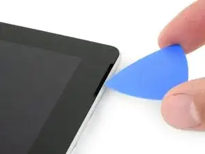
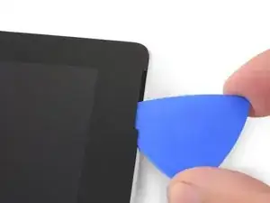
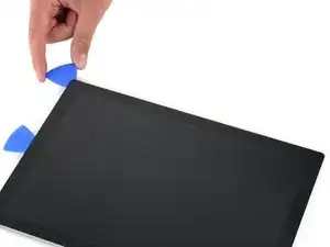
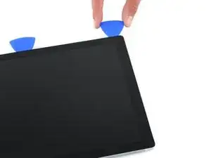
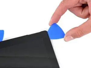
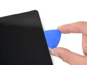
Infila un plettro nell'apertura dello speaker in alto a destra nello schermo e fallo scorrere tra il vetro e la griglia dello speaker.
-
-
-
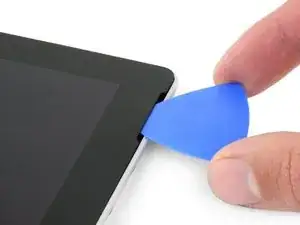
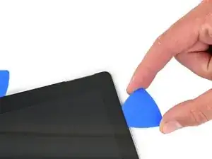
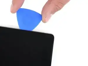
Ruota il plettro verso la parte inferiore del Surface per farlo scorrere sotto il bordo inferiore dell'apertura dello speaker.
-
-
-
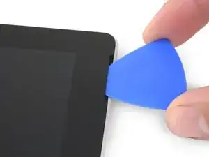
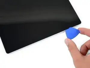
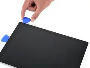
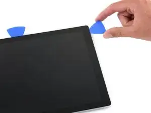
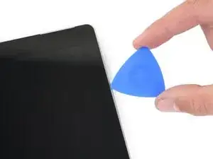
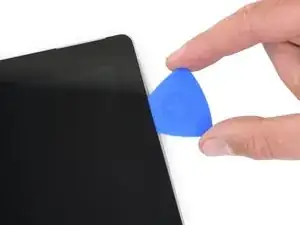
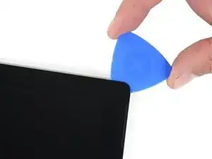
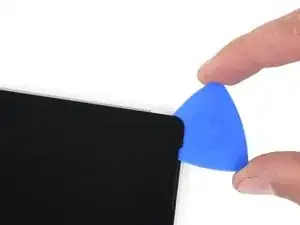
Fai scorrere il plettro sotto il bordo destro del Surface per tagliare l'adesivo sotto lo schermo.
-
Lascia questo plettro infilato sotto il bordo destro per evitare che l'adesivo si reincolli.
-
-
-
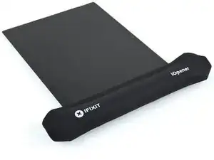
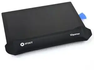
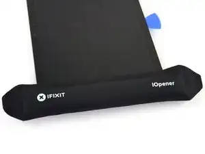
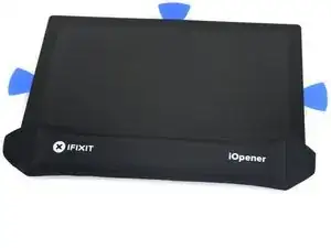
Riscalda il tuo iOpener ed applicalo al bordo inferiore dello schermo del Surface per due minuti.
-
-
-
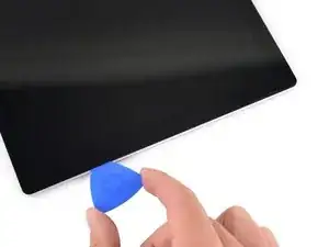
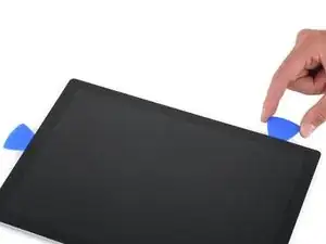
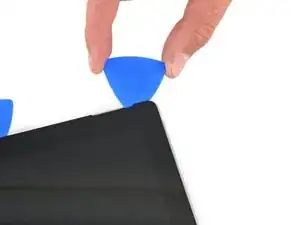
Infila un altro plettro sotto l'angolo in basso a destra e fallo scorrere attorno all'angolo, verso il bordo inferiore.
-
Fai scorrere il plettro sotto il bordo inferiore del Surface per tagliare l'adeesivo dello schermo.
-
Lascia questo plettro infilato sotto il bordo inferiore per evitare che l'adesivo si reincolli.
-
-
-
Scalda di nuovo il tuo iOpener e applicalo al bordo sinistro dello schermo del Surface per due minuti.
-
-
-
Infila un altro plettro sotto l'angolo in basso a sinistra e fallo scorrere attorno all'angolo, verso il bordo sinistro.
-
Fai scorrere il plettro sotto il bordo sinistro del Surface per tagliare l'adesivo dello schermo.
-
Lascia questo plettro infilato sotto il bordo sinistro per evitare che l'adesivo si reincolli.
-
-
-
Scalda di nuovo il tuo iOpener e applicalo al bordo superiore dello schermo del Surface per due minuti.
-
-
-
Fai scorrere il plettro attorno all'angolo sinistro e sotto il bordo superiore del Surface. Fermati quando il plettro è a 7,0 cm dal bordo sinistro.
-
-
-
Infila la punta di un plettro sotto lo schermo dove ti sei fermato nel tagliare. Non infilarlo più a fondo del bordo della cornice.
-
Ruota attentamente il plettro verso destra, premendo il lato lungo del plettro nell'adesivo dello schermo sotto la cornice, tagliando l'adesivo mentre procedi. Non far scorrere il plettro lungo il bordo del Surface.
-
Ripeti questa procedura di inserimento del plettro dove hai appena tagliato e rotazione verso destra sotto tutto il bordo superiore del Surface, finché il plettro si trova a 64 mm dal bordo destro del Surface.
-
-
-
Dopo aver tagliato sopra le antenne (22 cm dal bordo sinistro), fai scorrere il plettro sotto la parte restante del bordo superiore del Surface e attorno all'angolo in alto a destra per tagliare tutto l'adesivo rimasto.
-
-
-
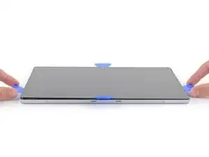
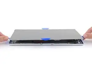
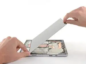
Solleva molto lentamente il gruppo dello schermo dalla copertura del Surface. Se incontri della resistenza, fermati e controlla che tutto l'adesivo sia tagliato.
-
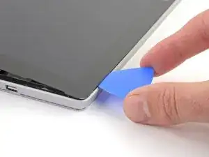
Usa un plettro per tagliare tutto l'adesivo rimasto.
-
-
-
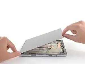
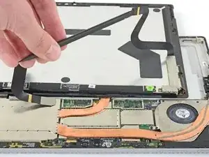
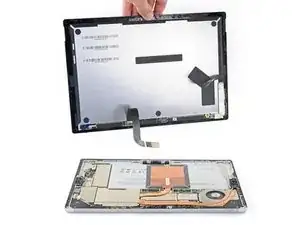
Solleva la parte superiore del gruppo dello schermo dal case mentre fai scorrere la parte inferiore dello schermo verso i connettori della scheda madre.
-
Appoggia delicatamente lo schermo sul case con i connettori rivolti verso l'alto. Stai attento a non piegare i cavi dello schermo.
-
-
-
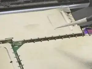
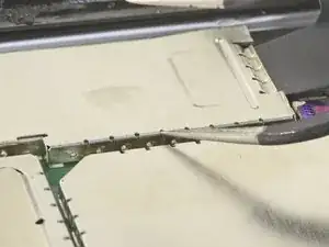
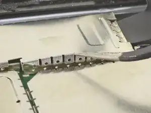
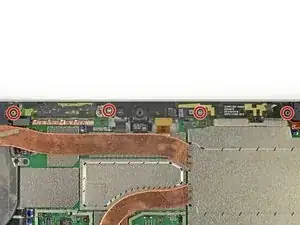
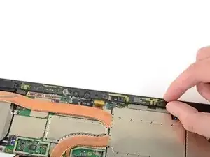
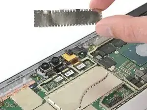
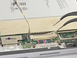
Usa la punta di un paio di pinzette per fare leva sulla schermatura EMI dalle aperture tra i "denti".
-
Ripeti questa procedura a diversi punti attorno al perimetro della schermatura finché non l'hai liberata.
-
-
-
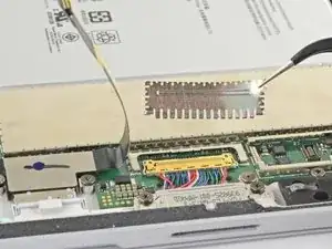
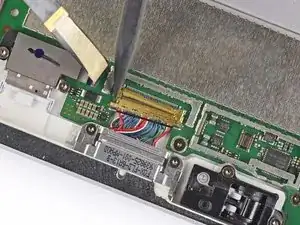
Usa le pinzette per rimuovere le due schermature EMI che coprono i connettori dei cavi dello schermo.
-
-
-
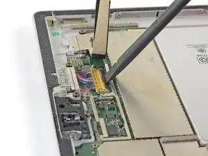
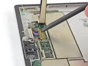
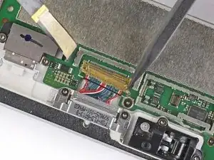
Fai leva con la parte piatta di uno spudger per scollegare entrambi i cavi dello schermo dalla scheda madre.
-
-
-
Rimuovi lo schermo dal Surface.
-
Durante il rimontaggio, fermati qui e segui questa guida per sostituire l'adesivo dello schermo.
-
-
-
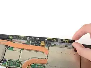
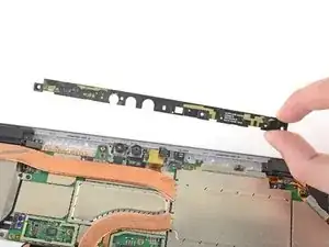
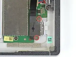
Utilizza un cacciavite Torx T5 per rimovere le quattro viti da 4,5 mm che tengono in posizione la staffa di supporto per l'antenna
-
-
-
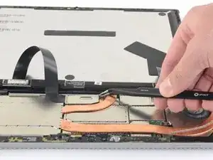
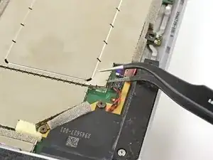
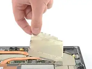
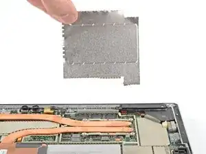
Infila una punta di un paio di pinzette appuntite in una fessura nell'angolo della schermatura EMI che copre il dissipatore.
-
Usa le pinzette per fare leva e sollevare la schermatura EMI dalla scheda madre il più possibile senza piegarla. Per ora non rimuoverla.
-
Stai attento a non forare la batteria con le pinzette mentre lavori sulla schermatura.
-
-
-
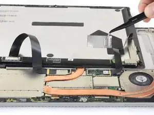
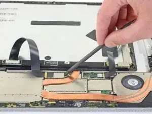
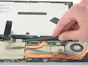
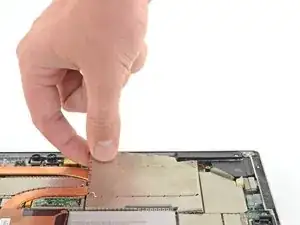
Ripeti l'ultimo passaggio in diversi punti attorno al perimetro della schermatura EMI che copre il dissipatore.
-
Rimuovi la schermatura della CPU.
-
-
-
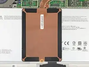
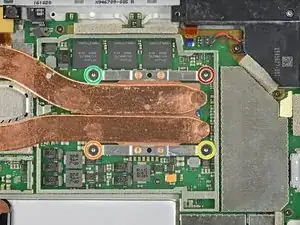
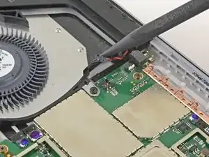
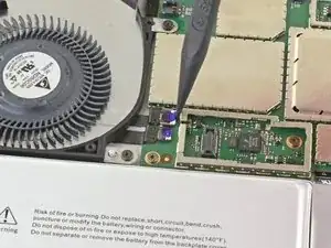
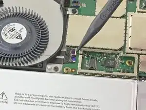
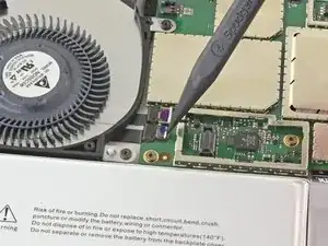
Usa un cacciavite Torx T3 per svitare le due viti dal dissipatore:
-
Una vite da 2,4 mm lungo il bordo superiore della placca rettangolare che copre la batteria
-
Una vite da 2,2 mm lungo il bordo inferiore della placca rettangolare che copre la batteria
-
-
-
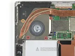
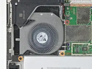
Usa un cacciavite a croce Phillips per svitare le tre viti da 2,4 mm che tengono ferma la ventola.
-
Usa un cacciavite Torx T5 per svitare l'ultima vite da 4,4 mm che tiene ferma la copertura della ventola.
-
-
-
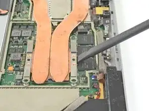
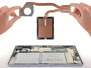
Usa un cacciavite Torx T5 per svitare le viti del dissipatore attorno alla CPU nel seguente ordine, un giro alla volta, finché non sono svitate:
-
Vite 1
-
Vite 2
-
Vite 3
-
Vite 4
-
Durante il rimontaggio, usa lo stesso metodo per avvitare queste vite, avvitandole una giro alla volta finché non sono salde.
-
-
-
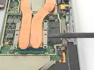
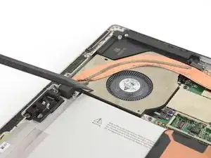
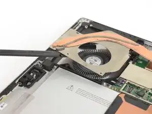
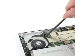
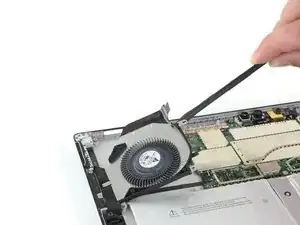
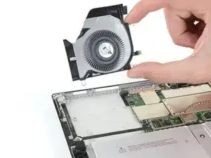
Infila la punta di uno spudger in un foro delle viti nella copertura della ventola e sollevala per separarla dalla ventola.
-
-
-
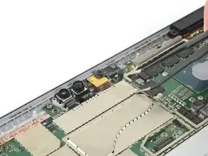
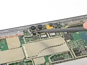
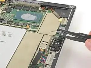
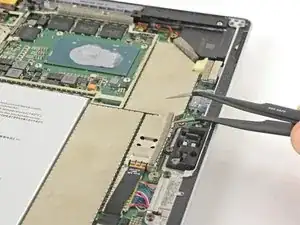
Infila una punta di un paio di pinzette appuntite in una fessura nell'angolo della schermatura EMI che copre i connettori della fotocamera.
-
Usa le pinzette per fare leva e sollevare la schermatura EMI dalla scheda madre il più possibile senza piegarla.
-
Rimuovi la schermatura EMI.
-
-
-
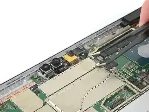
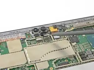
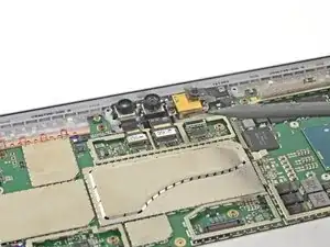
Fai leva con la punta di uno spudger per scollegare tutti i tre cavi delle fotocamere dalla scheda madre.
-
-
-
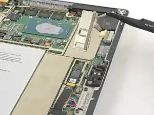
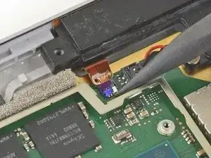
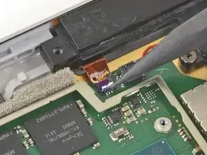
Usa la punta del tuo spudger per sganciare il connettore ZIF che tiene fermo il cavo dei tasti del volume/di accensione.
-
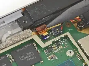
Sfila delicatamente il cavo dei tasti del volume/di accensione dal connettore ZIF.
-
-
-
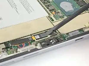
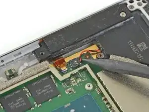
Infila la punta dello spudger tra i cavi dello speaker e la scheda madre fino a toccare il connettore del cavo dello speaker.
-
Prestando attenzione, fai leva sul connettore del cavo dello speaker per scollegarlo dalla scheda madre.
-
-
-
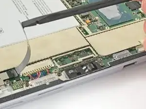
Usa la punta del tuo spudger per sganciare i connettori ZIF della ventola e della presa jack.
-
-
-
Usa la punta del tuo spudger per sfilare delicatamente i cavi della ventola e della presa jack dalle loro prese ZIF.
-
-
-
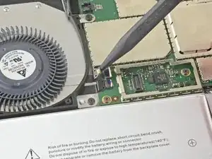
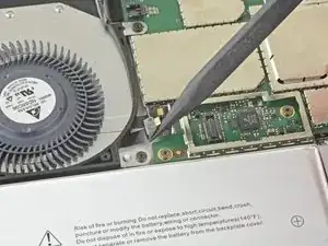
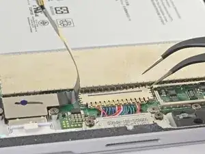
Usa un cacciavite Torx T3 per rimuovere queste vite dalla ventola:
-
Una vite da 2,5 mm
-
Due viti da 2,4 mm
-
-
-
Infila una punta di un paio di pinzette in una fessura nel bordo della schermatura EMI che copre il cavo ed il connettore del lettore della scheda microSD.
-
Usa le pinzette per fare leva e sollevare la schermatura EMI dalla scheda madre il più possibile senza piegarla.
-
Rimuovi la schermatura.
-
-
-
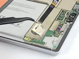
Usa la parte piatta del tuo spudger per sollevare il connettore del lettore della scheda microSD dalla sua presa.
-
Solleva il cavo del lettore della scheda microSD e spostalo dalla schermatura EMI che copre il gruppo della ricarica.
-
-
-
Infila una punta di un paio di pinzette in una fessura nel bordo della schermatura EMI che copre il connettore del gruppo della ricarica.
-
Usa le pinzette per fare leva e sollevare la schermatura EMI dalla scheda madre il più possibile senza piegarla.
-
Rimuovi la schermatura.
-
-
-
Usa la parte piatta di uno spudger per ruotare verso l'alto l'aletta di bloccaggio che tiene fermo il connettore del cavo del gruppo di carica.
-
-
-
Usa la punta di uno spudger per spingere attentamente entrambi i lati del connettore.
-
Alterna un lato all'altro, guidando delicatamente il connettore fuori dalla sua presa.
-
-
-
Usa un cacciavite Torx T5 per rimuovere le due viti da 3,1 mm che tengono in posizione il lettore di schede microSD.
-
-
-
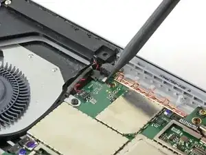
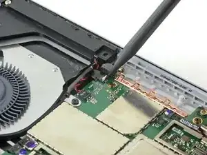
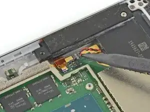
Usa la punta del tuo spudger per sganciare il connettore ZIF tra il processore e lo speaker destro.
-
Scollega il cavo dal connettore ZIF.
-
-
-
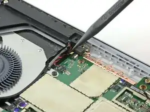
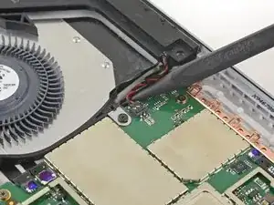
Infila la punta di uno spudger tra i cavi dello speaker destro e la scheda madre fino a toccare il connettore del cavo dello speaker.
-
Solleva attentamente il connettore del cavo dello speaker per scollegarlo dalla scheda madre.
-
-
-
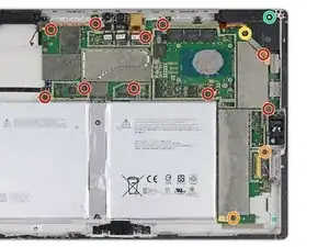
Usa un cacciavite Torx T3 per svitare le seguenti viti dalla ventola e dalla scheda madre.
-
Dieci viti da 2,4 mm
-
Due viti da 2,2 mm
-
Usa un cacciavite Torx T5 per svitare le due viti dello speaker destro:
-
Una vite da 4,2 mm
-
Una vite da 6,0 mm
-
-
-
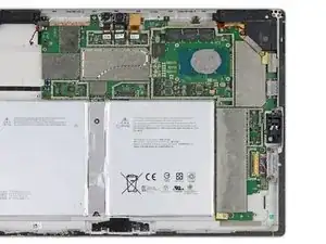
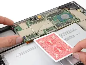
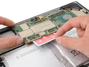
Solleva leggermente il lato sinistro della scheda madre.
-
Metti un carta da gioco o qualcosa di simile tra la scheda madre e il connettore.
-
-
-
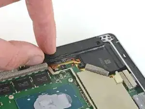
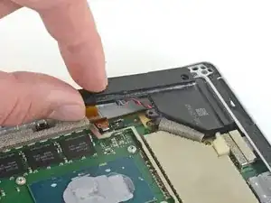
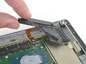
Prendi la sezione stretta dello speaker destro e sollevala leggermente.
-
Sfila lo speaker destro dalla copertura.
-
Rimuovi lo speaker destro.
-
-
-
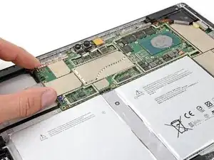
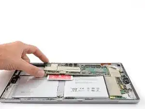
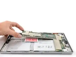
Rimuovi la scheda madre prima sollevando il lato sinistro ad un angolo di circa 30 gradi.
-
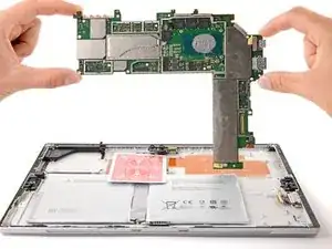
Sfila delicatamente le porte I/O sulla scheda madre dalle loro aperture e rimuovi la scheda madre.
-


Per rimontare il tuo dispositivo, segui le istruzioni in ordine inverso.
Porta i tuoi rifiuti elettronici a un riciclatore certificato R2 o e-Stewards.
La riparazione non è andata come previsto? Prova delle soluzioni di base ai problemi, oppure rivolgiti alla nostra comunità Risposte per trovare aiuto.

3 commenti
Super Anleitung !
Tst -
awesome info; used it to strip four "broken" tablets and reassemble as three working tablets (Schottky diodes and bad batteries)
Un genio, paso por paso, muy didactico como pracico! Gracias por toda tu informacion me he dado cuenta que es un trabajo muy meticuloso y no es para andar a la apuradas! Realmente muchas gracias
If I have a screen protector on the screen should I remove it? Will it interfere with the heating process?
IronJoker -