Introduzione

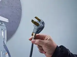
Use this guide to test the motor on your Whirlpool Dryer and replace it if necessary.

The motor turns the drum to tumble the laundry and drives the blower wheel to circulate air through your dryer.

If the motor fails, the dryer will not operate. Sometimes, the motor may hum but be unable to start. Since the motor is an expensive part, testing is recommended first.

This guide is rated as difficult not so much for the skill required as for the length of the guide and a few challenging steps, such as the lower front bulkhead.

This guide will work for most Whirlpool dryers. This guide is written with a model WED87HED dryer. If you have a different model, you may encounter some minor disassembly differences, but the overall repair process will be the same.

  1. cRUlfkgf2YwoDST3
    • Before you begin your repair, unplug your dryer.

    • Your power cord may have four prongs rather than three. The additional prong is a ground connection.

  2. u4WTU4KTBjf1GgPm
    u4WTU4KTBjf1GgPm
    KmGeNIaHMQTiHSWW
    UyNbTg6t3WxLV6FM
    • Throughout this guide, keep track of each screw and reinstall it exactly where it came from.

    • Use a nut driver to remove the screws securing the top panel to the rear panel bracket.

  3. gbDdHJLNo1Iiq3Y1
    gbDdHJLNo1Iiq3Y1
    vxW1WX6cffbgMuaD
    • Grasp the top and slide it 1/2 to 1 inch toward the rear of the machine.

  4. 2iNpUqjOIuDIiEQU
    2iNpUqjOIuDIiEQU
    IkW1XSsjMSmLOsT2
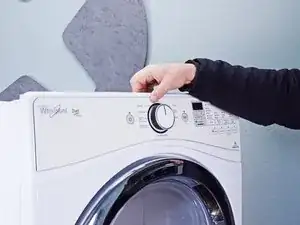
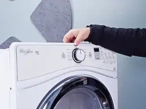
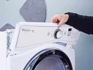
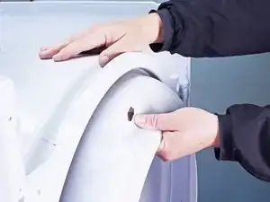
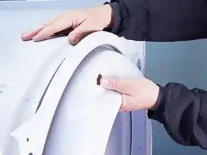
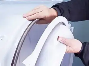
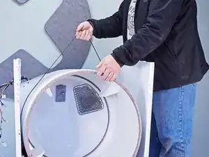
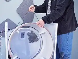
    • Lift the top panel upward to separate it from the chassis.

    • Remove the top panel from the machine.

  5. 4EqwYWjHdXpSDP2P
    4EqwYWjHdXpSDP2P
    I5XdQIMZQChnl4Ap
    • Disconnect the control panel cable from the main board.

  6. O21IMM2KKfDgSXgW
    O21IMM2KKfDgSXgW
    2i3v6ir4JGoNnvAC
    • Disconnect the drum light connector.

  7. vgpvSUy3LVl3MKa2
    vgpvSUy3LVl3MKa2
    5KH3EZG4GCmRwFVH
    • Remove the screws securing the control panel.

  8. oZUJsARu4qoKMFBq
    oZUJsARu4qoKMFBq
    OQBZEtdPmGqahirE
    kBuvEfxxfEZJiHPk
    • Lift the control panel up and tilt it away from the chassis to remove it.

    • Make sure to thread the cable through the hole in the chassis.

    • During reassembly, thread the cable through its proper hole before reinstalling the control panel.

  9. V2co3pYWneoWa61J
    V2co3pYWneoWa61J
    VUqqRMDJjqT2Ai4u
    VwHKBcRPmb1AUmwD
    • Use a small flat blade screwdriver or a spudger to unlatch both sides of the door switch connector.

    • Unplug the connector.

  10. QePkFLH1cNs1yBsK
    QePkFLH1cNs1yBsK
    Kk2pJqdhg4VTXol1
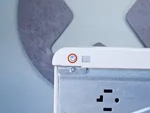
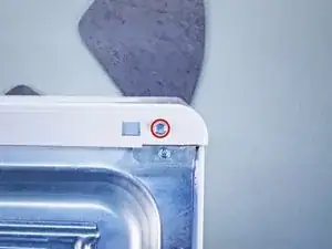
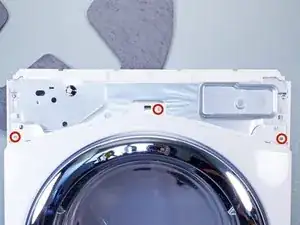
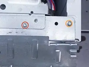
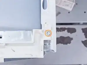
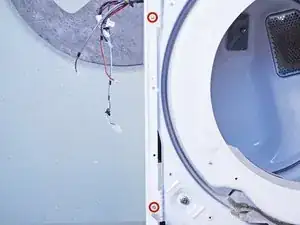
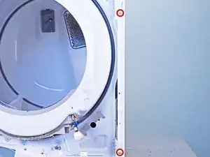
    • Remove the upper front panel sheet metal screws.

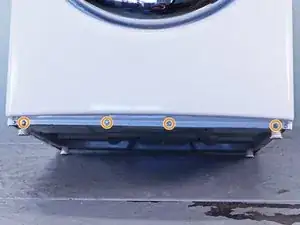
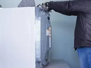
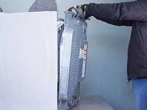
    • Tilt the machine backwards and prop it securely, or have a friend hold it.

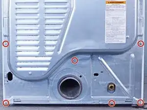
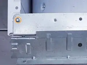
    • Remove the sheet metal screws on the bottom edge of the panel.

  11. dWOkVNOZkDNLaBf6
    • Remove the screws inside the door area below the drum opening.

  12. sdiCf4sNOddWCGtb
    sdiCf4sNOddWCGtb
    1yQ6y3WfZGi4oZSD
    m1XlPkKMN2aslONt
    • The panel is heavy and awkward. You may want to have a friend help you with this step.

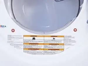
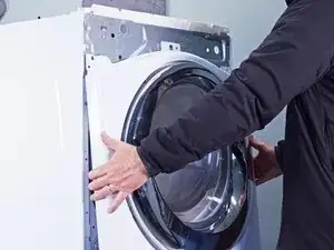
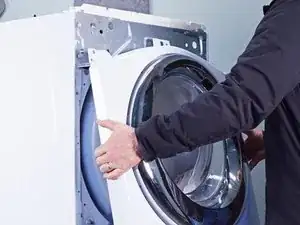
    • Pull the bottom of the panel away from the chassis about two to three inches.

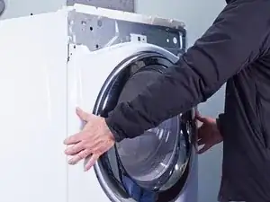
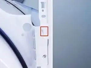
    • Lift the front panel off the small tabs on the chassis near the top of the panel and remove it.

    • Make sure you don't snag the door switch wire harness as you remove the panel.

  13. iFHOna1BIyCioX1h
    • Remove the cover plate screw.

  14. ATYQk5mB24lA3KPa
    ATYQk5mB24lA3KPa
    KeXHKQ4qTAEJrFBL
    MqMWNbLMQumnVG2d
    • Remove the cover plate.

  15. RvZLHJnHwNREikkH
    • Remove the screws securing the cord cables.

    • Mark the cables with a permanent marker if needed and take a picture or draw a diagram.

  16. XNtNBvTWyff5sjCS
    XNtNBvTWyff5sjCS
    iujv6sMmTmTOLdNM
    4NTgnK4UBNPllnpK
    • Pull the cord carefully down through the round hole.

    • Make sure you replace the connections correctly when you reassemble.

  17. jqyNtJRejYto6Qju
    • Remove the green ground screw.

    • Remove the cord terminal block screws.

  18. 4fxUgdAQpVHZDPiK
    4fxUgdAQpVHZDPiK
    YN4cgQTNFnGi2hEi
    IaF4lvHiVtIDuPLE
    • Move the cord terminal block behind the rear panel.

  19. GnGcGqxEc1nEJvUX
    GnGcGqxEc1nEJvUX
    ByuOEecsQBxpDQMH
    • Remove the rear panel screws.

    • Throughout this guide, keep track of each screw and reinstall it exactly where it came from.

  20. GO2EGBXmJjoGguZm
    GO2EGBXmJjoGguZm
    3wCTxnHVqQcZRCqT
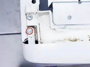
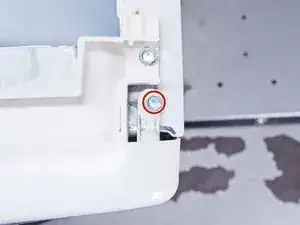
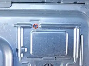
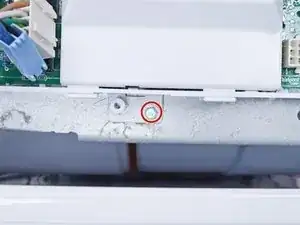
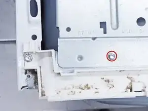
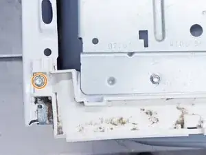
    • Remove the screw holding the main board bracket to the chassis.

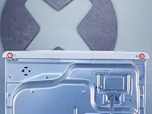
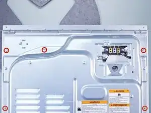
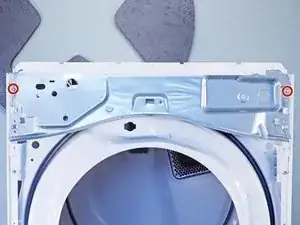
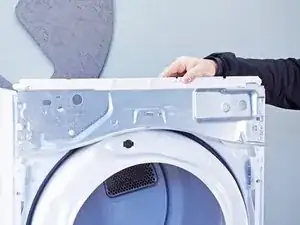
    • Remove the screws from the top rear of the machine.

  21. yF2gPkrEnXYrlhno
    yF2gPkrEnXYrlhno
    2fCyCuNe3q1nXrGy
    tFwGfKPAoOwGwsVX
    • Put on gloves before continuing, as the rear panel is sharp.

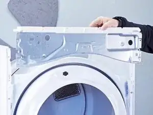
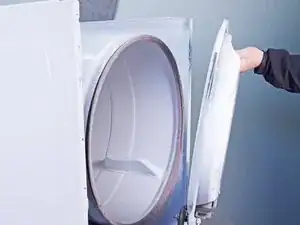
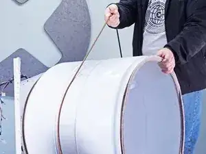
    • Lift the panel about 1/2 inch and tilt it to the rear to release it from the vent pipe.

    • Slide the panel off the vent pipe and remove it.

  22. HyZCKYcMrvXZWIfP
    HyZCKYcMrvXZWIfP
    hWFbDcAvvGgIonHg
    • During reassembly, perform the following:

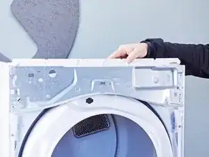
    • Make sure that the vent pipe is fitted into the collar on the panel.

    • Make sure the tabs at the bottom are aligned to the bottom rim of the chassis.

    • Position the panel so its screw holes match with the chassis.

  23. bBCon6w2G4mqCQqO
    bBCon6w2G4mqCQqO
    uEbKtyMWOSdiScaw
    ll5yb1HKbbTiJupL
    • Pull the lint filter up out of the lint filter slot to remove it.

    • These photos show the front panel in place, but the procedure is the same if the front panel is already removed.

  24. yNhxUKvx5bN1SHXm
    • Remove the mounting screws securing the lint filter housing.

  25. IUCCJuNWNrnnqLBH
    IUCCJuNWNrnnqLBH
    ftllH3yugLZuZNwb
    BwgTjTLnjY1gaHlO
    • Pull the filter housing outward from the chassis and down to remove it.

  26. EEjpo6hsXEtiDJMk
    EEjpo6hsXEtiDJMk
    nlS3iZtJTmcsrkoO
    EjR5f6qZKElMTHDh
    • Squeeze the locking tabs on the moisture sensor connector.

    • Disconnect the connector.

  27. m6IsuHVmdBMZcmTm
    • The blower cover is the round plate that serves as the inlet to the blower.

    • Unfasten the blower cover screw.

  28. PavjE3dyxZKOxoZb
    PavjE3dyxZKOxoZb
    5VHXtSJRYt3XK44A
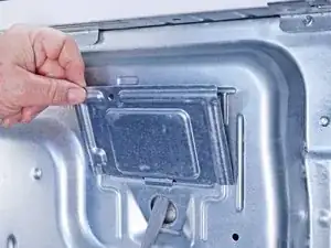
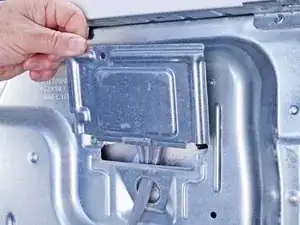
    • Lift the blower cover slightly and slide it to free the tabs which hold it in place.

    • Remove the blower cover.

    • The photos show the lower front bulkhead in place. The bulkhead doesn't affect the blower cover removal and reassembly.

  29. DasxXVvMC4NmIERH
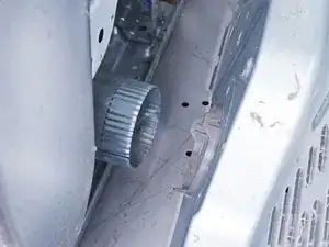
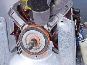
    • Move to the rear of the machine to access the drive shaft.

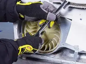
    • Hold the drive shaft with an adjustable wrench on the hex portion of the drum drive pulley.

    • The threads on the blower wheel are left-hand threads. The wrench must be installed to the left of the pulley to keep it from rotating counterclockwise.

  30. KuvMaSEHJHLOxJwa
    KuvMaSEHJHLOxJwa
    ngENWB1kVxmo25v1
    Yqq6Oeqw4hZtRWj5
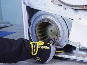
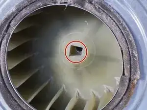
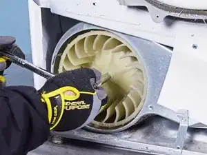
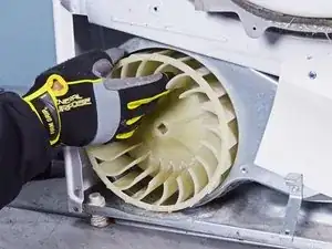
    • Use a socket wrench with an extension bar and no socket to fit into the square hole on the blower wheel.

    • Turn the wheel clockwise (to the right) to free it enough to remove it by hand.

  31. KbakMhSWcTontkmn
    KbakMhSWcTontkmn
    J1TQsoSSSTfUOET4
    FaIpLFMQETcwqODa
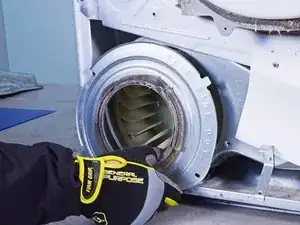
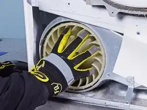
    • Rotate the blower wheel clockwise by hand until it's free from the motor shaft.

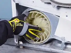
    • Remove the wheel from the blower housing.

  32. nqEpdV2Urv6RNYiE
    nqEpdV2Urv6RNYiE
    V613FIYtLgKlBJZY
    6Hvq3yfxnCiK3pVF
    • Label, photograph or make a sketch of the connector locations and of the main board bracket position on your machine.

    • Disconnect all of the connectors on the main board front half.

  33. VIey1RCWbNYUin1D
    VIey1RCWbNYUin1D
    BrWieVwFPIk6b3yo
    XDtlS4LHiKBVDja2
    • Label, photograph or make a sketch of the connector locations and of the main board bracket position on your machine.

    • Disconnect all the connectors from the rear half of the main board.

  34. ERmKF5SkMCEejkiP
    • Remove the sheet metal screw that retains the main board to the main board bracket.

  35. KVktIJhl1VXPDRHT
    KVktIJhl1VXPDRHT
    FyglGiaBjQEHypfb
    KgCSXL1BhYvFOsyH
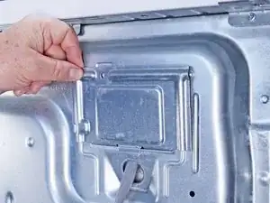
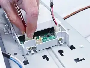
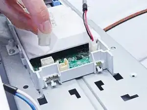
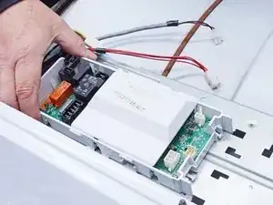
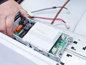
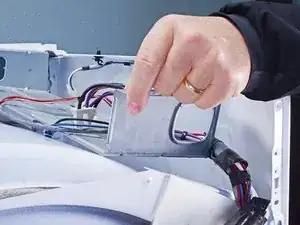
    • Lift the rear corner of the main board nearest to the side walls of the chassis.

    • You want to release the locking tab on the side of the main board.

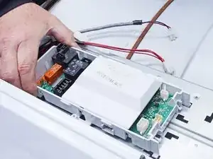
    • Slide the main board toward the front of the dryer to release the tabs securing it to the main board bracket.

  36. PyYOBF1rvuiosY6h
    • Remove the main board from the main board bracket.

  37. XHkGC56UFCdPKEAX
    • Remove the sheet metal screw holding the main board bracket.

  38. lXiXILgdXUD2VByW
    lXiXILgdXUD2VByW
    TBJbljNvQtZhCt1j
    FuCucb2J4APLWILC
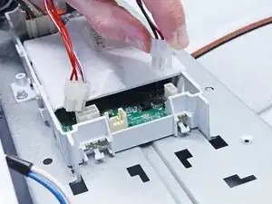
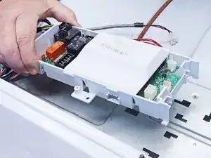
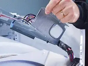
    • Lift off the main board bracket from the chassis and turn it so the bottom is exposed.

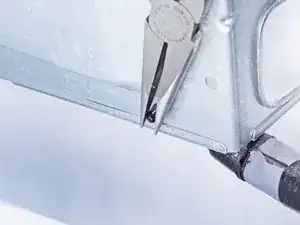
    • Using long nose or slip joint pliers, pinch the locking wings of the harness retainer clamp.

    • Separate the harness from the main board bracket and remove the main board bracket.

  39. cdIExuejspidmTrE
    cdIExuejspidmTrE
    o5AC3ZyICGPadfan
    2EQTyFOqFtOTcbPd
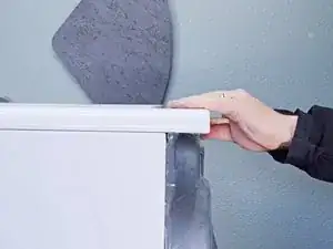
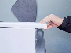
    • Remove the screws securing the upper front bulkhead to the front of the chassis.

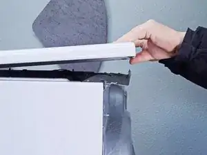
    • Remove the sheet metal screws securing the top plastic portion to the upper front bulkhead.

  40. dGNHS2YJqwpsIJF2
    dGNHS2YJqwpsIJF2
    kQGYVctCpLGysjVu
    wDX3HVi33pRRHkmw
    • Remove the upper front bulkhead and set it aside.

  41. dTmUm1QImRlmENy1
    dTmUm1QImRlmENy1
    6aqyrUccUhUWpmO2
    URLXCn3Ciu6ZPeEp
    • Take careful note of the belt path before proceeding.

    • Be careful during this procedure! The idler arm is under spring tension and may pinch you, or it could damage the belt switch if the arm is allowed to snap down.

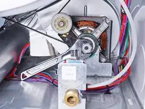
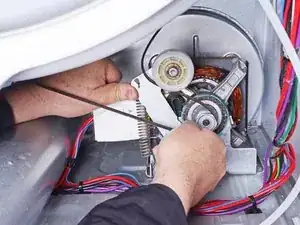
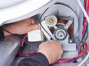
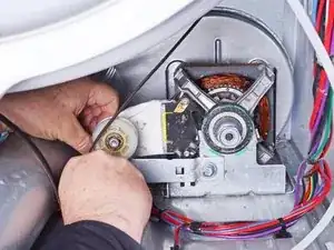
    • Push the idler arm (the metal upside-down "L") up to relieve the tension on the drive belt.

    • Remove the belt from the motor pulley.

    • Gently lower the idler arm until it rests parallel to the dryer floor.

    • During reassembly, refer to your notes or the belt path link to rethread the drive belt.

  42. BfLDAdStt6C6AilR
    BfLDAdStt6C6AilR
    Xu5Mulp3NeTeQZDB
    • Remove the screws securing the lower front bulkhead.

  43. YNRkHHRX11BOrUde
    YNRkHHRX11BOrUde
    SPiiMAbZsXLojVQq
    HBh6rOKsAYBQfXpS
    • While supporting the drum, lift the lower front bulkhead off of the hooks on the chassis.

  44. 2MRcZaGBOiSUY3ZH
    2MRcZaGBOiSUY3ZH
    BKOvKwKvB3POVVBU
    mGnURMLGb4KHrMeZ
    • Lower the bulkhead about 2 inches to free the drum rollers tucked under the drum.

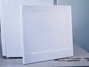
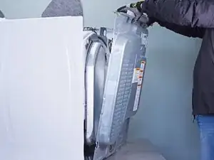
    • While supporting the drum, remove the lower front bulkhead.

    • During reassembly, tilt the bulkhead to the right to get the rollers under the lip on the front of the drum. Once the drum is on the rollers, you can move the bulkhead to the upright position.

  45. kBHXgsbSAEp51QdS
    kBHXgsbSAEp51QdS
    qrrRBPlLvTAjYAJY
    Ex1XNZXMLBIQ3tl3
    • Use the belt to lift the drum a few inches.

    • Swing the drum out of the front of the dryer.

    • Note which end of the drum faces the front.

    • If the belt is broken, stand in front of the drum and put your arms inside it. Lift it up and pull it through the front opening of the machine. Having someone to help you with this is a good idea.

    • Make sure you get your drum back on the rollers when you reinstall the lower front bulkhead. Take your time and don't force it.

  46. j5WuYKZKI1NqScK5
    j5WuYKZKI1NqScK5
    Qk1fOAmrkBw2Ogq6
    • This step shows the thermal fuse location and appearance.

  47. mDXDPYf63yRakYXo
    mDXDPYf63yRakYXo
    JW1EYP5mQSXJVhZg
    rJLsZC3BTrx4xDM6
    • Disconnect the two spade connectors attached to the thermal fuse.

    • Always remove wires by pulling on the connector, not the wire.

  48. dDnjrG22SU1FSWVK
    dDnjrG22SU1FSWVK
    XDO1xt4eKY5THQYE
    3YfkvSulBHtLCrBU
    • Disconnect the two spade connectors attached to the outlet thermistor.

  49. G36hGumqrDYlOfD6
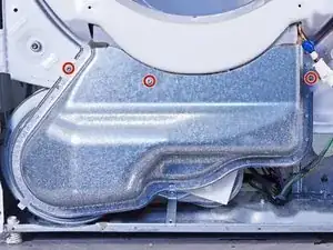
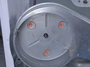
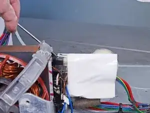
    • Remove the sheet metal screw securing the vent pipe to the blower housing.

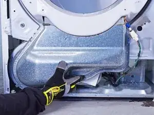
    • Remove the vent pipe by sliding it toward the rear of the dryer to free it from the blower housing.

  50. cNheZoYLKYlFDdBJ
    • Remove the sheet metal screws securing the blower housing.

  51. UQRT5fxXJRDVaytN
    UQRT5fxXJRDVaytN
    jRPvHgVLaADuFTIA
    cmj2U2JcCiVZTJoC
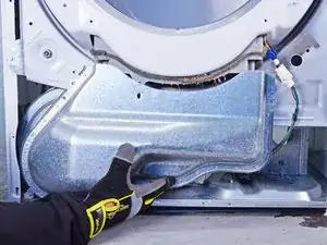
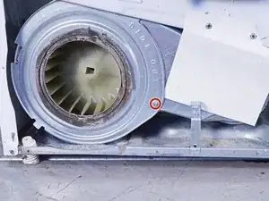
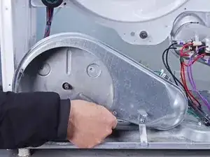
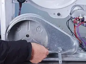
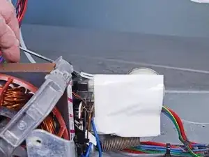
    • Move the blower housing toward the front of the dryer about 1–2 inches to clear the motor shaft.

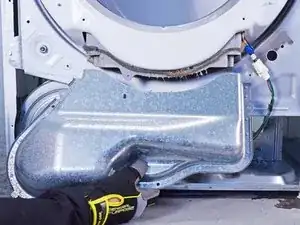
    • Lift the blower housing up and away to remove it.

  52. maOAMWK3TdDMkXLw
    maOAMWK3TdDMkXLw
    JTrl3OkNCPBfEG1E
    RKsM2GEUkkFsOxOe
    • If you are just removing the motor without testing it, skip the next three steps.

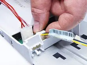
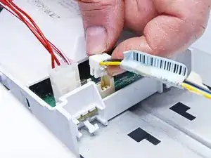
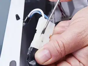
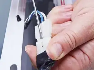
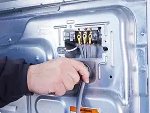
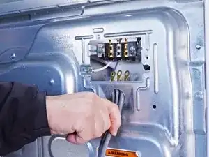
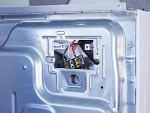
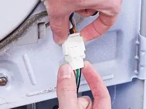
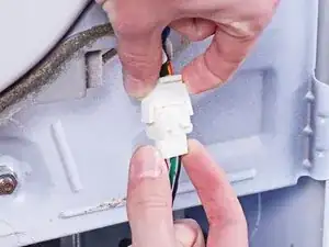
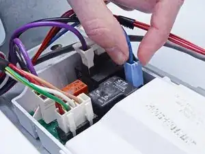
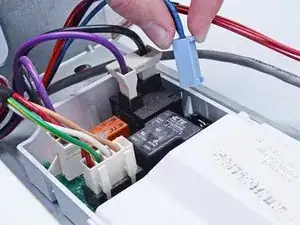
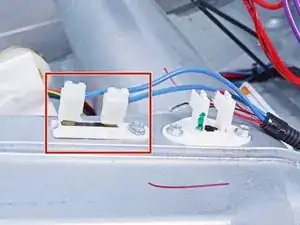
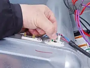
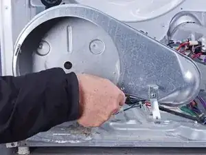
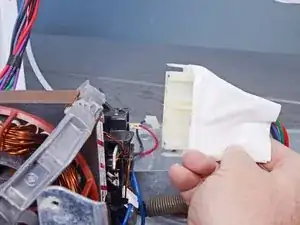
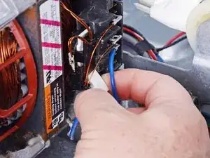
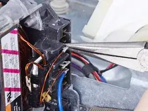
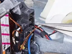
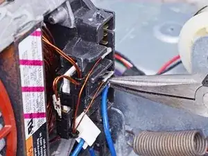
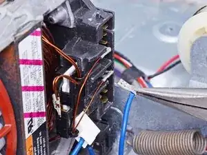
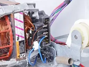
    • Use a flat blade screwdriver or a spudger to lift the connector locking clips. Make sure to release both the top and bottom clips.

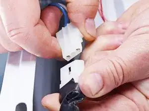
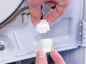
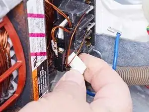
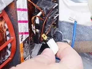
    • Disconnect the connector by pulling it straight off.

    • Be sure to grip the connectors and not the wire when disconnecting.

  53. 24oSIho33C6fpZOS
    24oSIho33C6fpZOS
    65ODobgCH2KwEITi
    HwtjXfaHqOgyDM1v
    • You will need the wiring schematic for your dryer to figure out what terminals are for the start winding. Usually one of those terminals will be common with the run winding and will be connected to the belt switch.

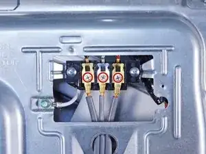
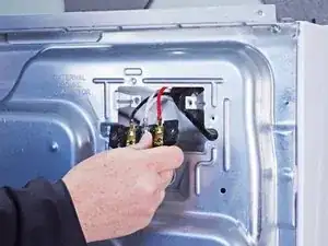
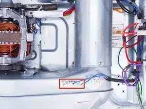
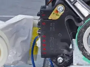
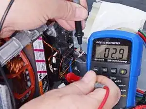
    • For the next three steps, refer to the first image for the terminal numbering.

    • On our example machine, the terminal that is common between the main and start windings has the blue wire with the white connector at an angle (the only one).

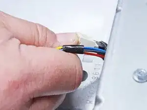
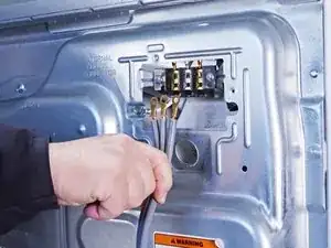
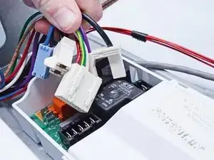
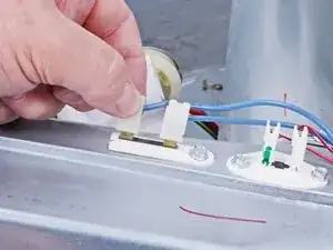
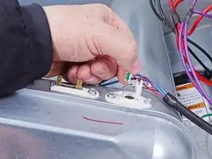
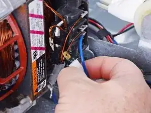
    • Disconnect the common terminal.

    • Be sure to grip the connector and not the wire when disconnecting.

  54. kF4WXkHuBnmmLUln
    kF4WXkHuBnmmLUln
    L2MfLSfNMGaXuESV
    AIZBCUWMqHdfbkXk
    • This step will require a multimeter. If you aren't familiar with how to use one, here is a guide that will help you.

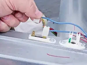
    • Disconnect the wire that is connected to the start winding that you located on the schematic. On this machine, it is aligned with terminal 3.

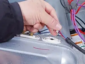
    • Measure the resistance from the start winding wire to the common terminal shared between the start and run windings. Use the lowest resistance setting (usually Rx1) on your multimeter if you need to set it manually.

    • The value should be 2–5 Ω. If it's outside that range or OL, the motor is defective and needs to be replaced.

  55. vDHl3FOZtHpBcZyv
    vDHl3FOZtHpBcZyv
    W42CNeUJUBA5p3pF
    oFXue5jbq4dcTlty
    • You will need the wiring schematic for your dryer to figure out what terminal is for the run winding. On our example machine it is aligned with terminal 5.

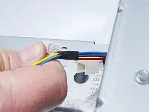
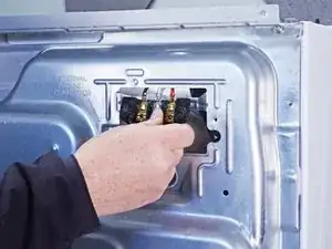
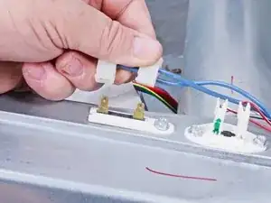
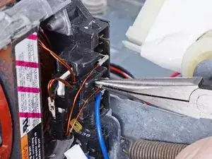
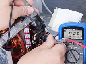
    • Disconnect the run winding wire.

    • Be sure to grip the connector and not the wire when disconnecting.

    • Measure the resistance from the run winding terminal to the common terminal shared with the start winding.

    • This reading should be 2–5 Ω. If it is outside this range, the motor is defective and should be replaced.

  56. KYKdfmDVhEeiExVU
    KYKdfmDVhEeiExVU
    JyGoRWRc1RfTOHqP
    • Disconnect the belt switch wire from the motor.

  57. aWkA4r4oe3TZRX5N
    aWkA4r4oe3TZRX5N
    NeEPPZvMTKTgN3jX
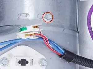
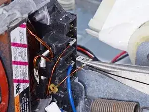
    • If it isn't already disconnected from checking the windings, disconnect the other belt switch wire from the motor.

    • Be sure to grip the connectors and not the wire when disconnecting.

  58. KPl4vaQ43lAXLMEw
    • During reassembly, refer to this photo for where to reconnect the wires.

  59. P2OH5MRXwKhi2xuO
    P2OH5MRXwKhi2xuO
    tusxfTMLYe23tLpb
    OLbSIHo3oMM2ZNf4
    • The next steps will show how to replace the motor.

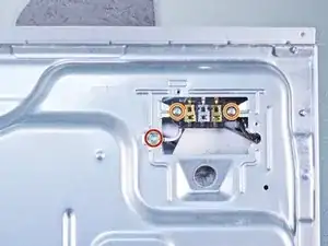
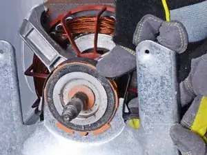
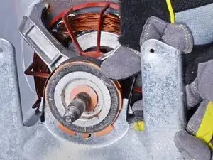
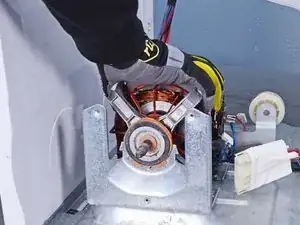
    • With one hand, press down on the motor retainer clip at the bump on the clip. This should make it easy to unhook the clip from the motor cradle mount.

    • While maintaining the downward pressure, use your other hand to unhook the clip from the motor cradle mount.

  60. 2MAoXdrk2qHKKHvO
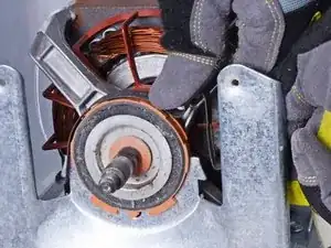
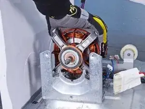
    • Lift the motor retainer clips off the motor and remove it.

    • Repeat the last two steps for the other motor clip.

  61. r5vCZKiaZmRSLIoP
    r5vCZKiaZmRSLIoP
    tedxeOdKZIUik2MX
    • Lift the motor out of the motor mount and remove it.

Conclusione

To reassemble your device, follow these instructions in reverse order.

Repair didn’t go as planned? Ask our Answers community for help.

Bill Gilbert

Membro da: 30/06/22

29837 Reputazione

0 commenti