Introduzione

This repair guide was authored by the iFixit staff and hasn’t been endorsed by Google. Learn more about our repair guides here.

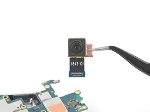
This guide shows how to remove and replace a defective rear-facing camera module for a Pixel 3 XL.

To remove this camera, you will need to loosen and partially remove the motherboard.

  1. wIigbvaXNQ1gCfa2
    wIigbvaXNQ1gCfa2
    4f3uBiUqnYIwtpHk
    5fCoAkkaQhAC1YlB
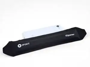
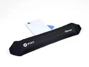
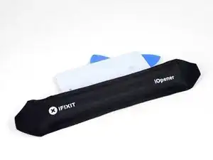
    • Heat an iOpener and apply it to the right edge of the back cover for a minute.

    • A hair dryer, heat gun, or hot plate may also be used, but be careful not to overheat the phone—the display and internal battery are both susceptible to heat damage.

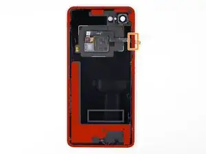
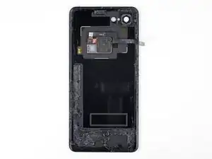
    • While you wait, note the following areas on the back cover:

    • Strong adhesive—there are large patches of adhesive near the bottom of the phone.

    • Fingerprint sensor cable—be careful not to slice through the cable as you pry

  2. cZhYNQPJKIpeBdUV
    cZhYNQPJKIpeBdUV
    O3ZtiUsIEYd1LOi5
    PdMr62SQHqkykS2M
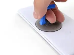
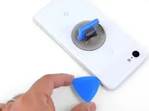
    • Apply a suction cup to the heated edge of the back cover, as close to the edge as possible.

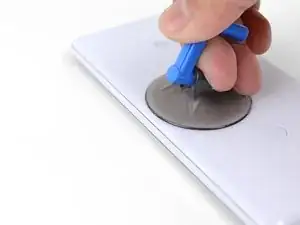
    • Pull up on the suction cup with strong, steady force to create a gap.

    • Depending on the age of your phone, this may be difficult. If you are having trouble, apply heat to the edge and try again.

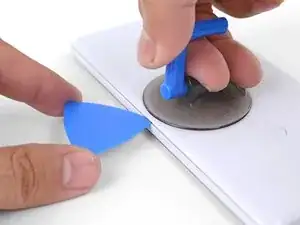
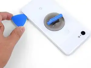
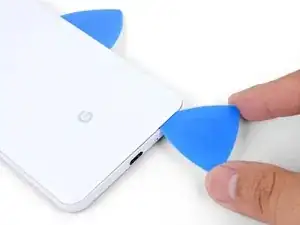
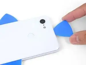
    • Insert the point of an opening pick into the gap.

    Suction cup doesn’t work on severely cracked glass.

    Jeffrey Kongthong -

    Step 1 - 2 took me about 50 minutes. Back and forth with heat and trying with suction cup. I could get my finger nail in but not the pick. Took two people, but we finally got a pick in. 2 year old phone.

    Andrew Messier -

    Took about 15 minutes and three total attempts. On the third attempt, I also used a thinner, metal, pick to widen the gap just enough for the plastic pick to fit (Though be careful as you can easily break it with a metal pick). The phone is three years old.

    Hotohori -

    Could not get in with the pick or in from the side. Targeted the bottom of the phone with the iOpener and managed to gently create some space for the pick with the opener tool.

    Daniel R. -

    I also struggled here for a while. I ended up working my way around the entire edge of the phone until I found one spot where I could pry up the back panel. I used a jimmy instead of the opening pics. I also used a hairdryer on lower heat instead of the iopener. 3 year old phone.

    Bryan Wethington -

    Took 30 minutes + to get the back cover off. Used another suction cup to grip from the busted screen and the ifixit suction cup for the back. A thinner Acoustic guitar pick was required opposed to the standard Blues picks provided in the kit (har-har). Would HIGHLY suggest getting a pick into both the back and the front before removing the panels as it will give you more surfaces to pry from. Made that mistake...

    Brian Sommer -

    Over 2 hours of trying, I keep reheating the pouch and let it sit on the edge for sometimes up to 10 minutes since the directed 1 minute wasn't working. Physically cant get enough leverage on the back of the phone; picks are too thick to get under the crack, and the suction cup pops off before I can get enough force to see any gap open. Phone is 5 years old. I really need some help

    Grant Cooper -

    Hey Grant!
    I hear your pain—the adhesives on this phone are very strong. The initial gap is one of the hardest parts of the procedure. Here are some suggestions:
    * If you have a hair dryer, give that a shot. Heat the edge until it is slightly too hot to the touch.

    * These adhesives separate not with extreme force, but with constant steady force and time. Try heating the edge and pull on the suction cup with firm force for about a minute to let the adhesive separate.

    * If you have an opening tool, you can try this procedure to get the initial gap.

    Arthur Shi -

  3. ecDEBpnvfOTcMLZ2
    ecDEBpnvfOTcMLZ2
    2uOnUFqafrCYXyEN
    p51ClEsXXIXPIR4Z
    • Slide the opening pick along the right edge to slice through the adhesive.

    • The adhesive gums up and becomes hard to slice once it cools. If that happens, re-apply heat to the edge to make slicing easier.

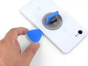
    • Once you have sliced through the edge, leave an opening pick in the seam to prevent the adhesive from re-sealing.

  4. KQZNiMIXEoEv3sQA
    • Apply a heated iOpener to the bottom of the back cover for a minute.

  5. gBLNTMRXodCAlNJR
    gBLNTMRXodCAlNJR
    Vbq4vFubRlSHJKRY
    4UK5LbKHwIXueBJp
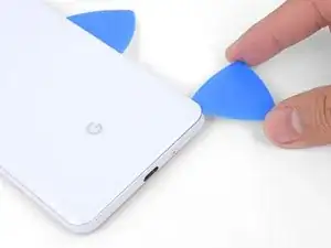
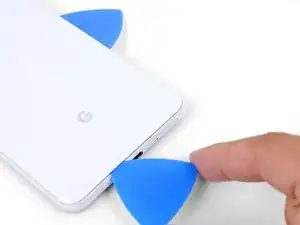
    • Use an opening pick to slice around the bottom right corner and continue along the bottom edge of the phone.

    • Work slowly as you slice around the corner to prevent the panel from cracking. If the slicing becomes hard, re-apply heat.

    • Leave a pick in the edge to prevent the adhesive from re-sealing.

  6. K1DNALhsFYem6WuY
    K1DNALhsFYem6WuY
    2FCl2jg2ZVTGSvUm
    IXQXmHMoJGXm3PXr
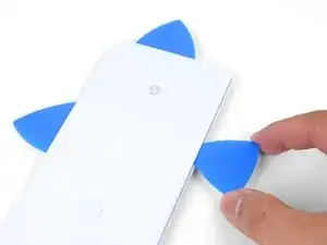
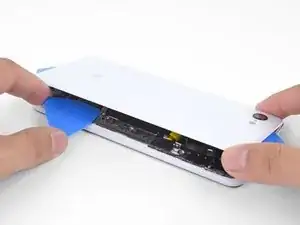
    • Continue heating and slicing the remaining edges of the phone.

    • Be careful as you slice along the left edge of the phone. If your pick feels like it's stuck near the top, you may have snagged the fingerprint sensor. Retract the pick out of the seam slightly and try again.

    • Be sure to cut through the thick portions of adhesive near the bottom and right edge of the phone.

    The back cover is Glass!!!!. DO NOT PRY HARD, IT WILL BREAK!!!!!!!

    You must go slowly and let the heat do the work, if you force the cover off, it will shatter.

    Paul Bernstein -

  7. USkM2UJmmdDVnTmv
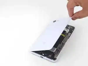
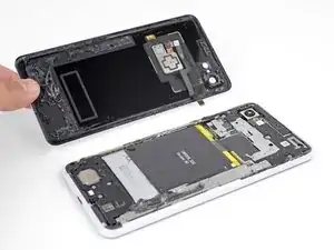
    • Gently pry up the right edge of the back cover.

    • Use an opening pick to slice through any remaining adhesive along the edges.

  8. 1nxmI4hs2Gymfag5
    1nxmI4hs2Gymfag5
    M4kcSI5plQnJtuT1
    MBJ2GPSSE3RnNtLF
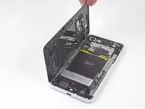
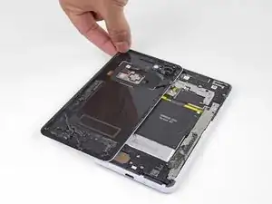
    • Swing the right edge of the back cover upwards and rest the flipped panel along the left side of the phone.

    • Be sure to maintain slack on the fingerprint sensor cable and prevent it from being pinched.

    • During reassembly, this is a good point to power on your phone and test all functions before sealing it up. Be sure to power your phone back down completely before you continue working.

    • During reassembly, follow this guide to install custom-cut adhesives for your back cover.

    • If you replaced the fingerprint sensor, you'll need to use this software tool to make the phone recognize the new sensor.

    Reassembly is way harder. The adhesive guide is generic and not super helpful, so don't be surprised if things went smoothly until you get to this step and then everything starts sticking to things its not supposed to.

    Christopher Trimby -

    This is great but how you address that fact that the phone is tied to a particular fingerprint sensor and after replacing, the new sensor is not recognized by the original phone?

    Dave -

    Hi Dave!

    There's a software calibration tool that you can use to calibrate your new fingerprint sensor. I've updated this step to include a link to the tool.

    Arthur Shi -

    I have a pixel 3 xl and I can't get the tool to work. I finally got the driver's installed after several hours and it says it's for pixel 6 and up basically. So I tried the other option and it's basically saying to do a factory reset? Did I mess something up on the install or what am I doing wrong here? Thanks

    Cody L Paulsell -

    Uhhh

    So, apparently the connector on the motherboard for the fingerprint sensor is just ridiculously fragile, because after plugging and screwing everything in (pretty much reassembled except for the adhesive), I closed up the phone and powered it on to test if everything was working, and when I opened it back up and let the top hang off to the side, it just snapped off. I didn't even have it tensioned that much, it was just hanging off to the side and snapped. So now I've traded a non-functional camera with a non-functional and irreparable (unless I get a new motherboard) fingerprint sensor.

    The guide really ought to emphasize how delicate that connector really is. I have a google drive link here to a photo of the remnants of my poor fingerprint sensor connector :( link

    Mindle -

    Wasted a ton of time and effort (and money) trying to use this guide to repair my Pixel 3XL. Then I get to the software calibration tool and find:

    Unsupported device

    This is not a compatible device. Only Pixel 6, 6 Pro, 6a, 7, 7 Pro, 7a devices can install this software.

    I cannot say how frustrating it is when a guide and website that tried to be so helpful ends up like this. Failure due to referencing tools not on the site and not suitable for the job.

    Ross Chesley -

  9. 66BxIa114CvPBDXF
    • User tweezers to carefully peel up the yellow tape over the fingerprint sensor connector.

    This step is utterly unnecessary. It achieves nothing, and the tape is there for a reason (I'm not sure why, maybe to prevent short circuits). I didn't remove this tape while disassembling and it didn't change anything.

    Krzeszny -

    The Kapton tape should adhere to both the cable and the connector. It helps prevent the cable from slipping out of the ZIF connector. You're right in that you don't have to completely remove the tape—I've adjusted the step to reflect this.

    Arthur Shi -

    I just finished this guide, thank you. It would be nice to have a "before ribbon removed" reference picture that's also without the Kapton tape in place if possible. I was no longer certain how far back into the ZIF connector I had to place the ribbon cable as I simply forgot what it looked like before removing it. Basically, it "felt" like it was out too far, but since I had no reference I couldn't compare. Step 10 has good close up pics, but the ribbon cable is already out a bit so a bad reference.

    teknomedic -

  10. sIaa2bIVcTWtgVNZ
    sIaa2bIVcTWtgVNZ
    kljONWUpcx2eLE4p
    syrHkK1ndwxqPAh2
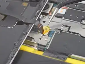
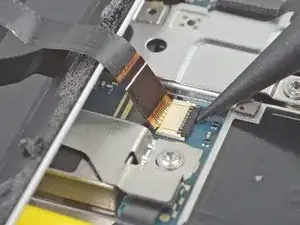
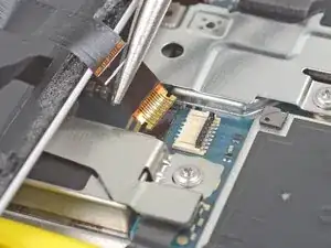
    • Use the point of a spudger to carefully flip up the black lock bar on the fingerprint sensor's ZIF socket.

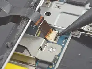
    • Grasp the cable's tab with your fingers or tweezers and gently walk the flex cable out of the socket.

    • To prevent shorting, be careful not to touch the metal contacts on the flex cable with your tweezers.

  11. KOLMNRDZQHXDXx2H
    • Remove the back cover.

    • Follow this guide to correctly apply new back cover adhesive.

  12. ZRoNSKDIlMf5W2Yh
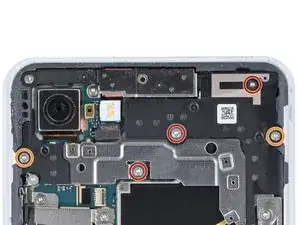
    • Remove the following four T3 screws securing the metal cover bracket:

    • Three 4 mm long screws

    • One 3 mm long screw

    • Throughout this repair, keep track of each screw and make sure it goes back exactly where it came from.

    Be careful when putting the screws back in that you do not over tighten. This will cause you to destroy some pixels on your screen.

    Brian Retterer -

    The long screw on my disassembly was adjacent to the lettering for the Qi inductive receiver, and not close to the silver exposed part of the battery as indicated

    Andrew Munro -

    In my case, all the screws are the same length.

    Krzeszny -

  13. iMjRoXXfrrJG6TTj
    iMjRoXXfrrJG6TTj
    EbGvs3NuseOA34IT
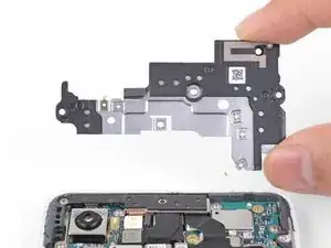
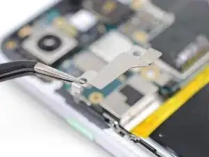
    • Insert the flat end of a spudger underneath the top right edge of the metal bracket and pry up to loosen it.

    • Remove the metal cover bracket.

    There is a small adhesive pad under the metal bracket, between the two middle screws that will provide some resistance when lifting the metal cover bracket

    Andrew Munro -

  14. 2FT5FhK5JAiFdDI6
    2FT5FhK5JAiFdDI6
    Ll1pjbf2FDCAQSUM
    Q2TwemRwJ1F5JGut
    • Use the point of a spudger to pry up and disconnect the battery connector from its socket.

    • Do not use metal tools to to disconnect the battery, or you will risk shorting the battery.

    • Bend the battery cable such that the connector will not accidentally touch the socket.

  15. uIblmnHfCqI1UmDi
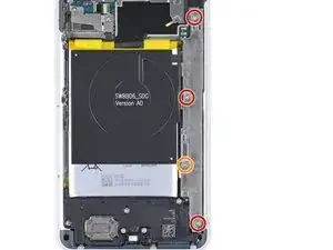
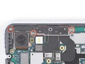
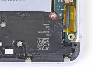
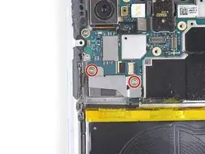
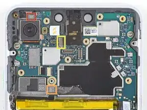
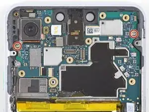
    • Remove the five T3 screws securing the motherboard shield:

    • Three 4 mm long screws

    • Two 3 mm long screws

  16. UJIvtcPDVyQ2ws6B
    • Remove the motherboard shield.

  17. VanRBMIYMGegICCg
    • Remove the three 3 mm long T3 screws securing the front camera bracket.

    Important note! In this step the 3mm screws are highlighted in red, instead of orange like the rest of the steps, don’t make the same mistake I did and not catch that!

    David -

  18. FDRZvPAYWq13yvoH
    • Remove the front camera bracket.

  19. QxEwImNnJIXVCTOp
    • Determine which camera you wish to replace:

    • Normal angle camera

    • Wide angle camera

  20. qbmtvJ4FPpSFc5uf
    qbmtvJ4FPpSFc5uf
    XxkYLLCRNLd14a3H
    fo4Jie1XoDDdKs3r
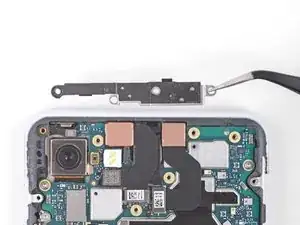
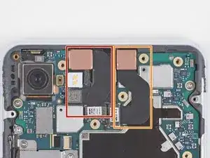
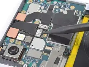
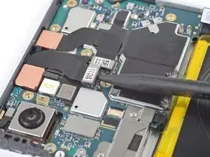
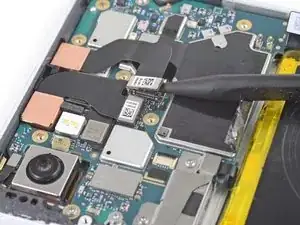
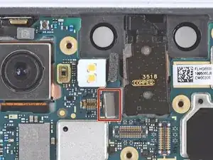
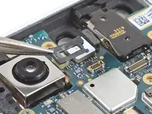
    • Use the point of a spudger to carefully pry up and disconnect the cameras from their motherboard sockets.

    • Be very careful not to dislodge the small surface-mounted components surrounding the sockets.

  21. EtCHJifOSAXKfV3F
    EtCHJifOSAXKfV3F
    Don4WbX4rQn4RkVQ
    ANO4aEfpqKkKyGpJ
    • The cameras are lightly adhered in place.

    • Use the flat end of a spudger to pry up and loosen the camera modules from their recess.

  22. UA6WnowKKMvlET3S
    • Remove the front-facing cameras.

  23. wNQh4wW5wHyyJPQp
    • Remove the 4 mm long T3 screw securing the top-right corner of the loudspeaker.

    • Removing this screw will give you slightly more wiggle room when removing the motherboard.

  24. cpDxGxKkmGjtRxCN
    • Remove the two 3 mm long T3 screws securing the button array connector bracket.

  25. NJIvDyxYQFcLryl1
    • Remove the button array connector bracket.

  26. prZTqZDDrTnyP6M5
    prZTqZDDrTnyP6M5
    tRs5LqWQDHpxfimj
    • Use the point of a spudger to pry up and disconnect the earpiece connector from its motherboard socket.

    • Carefully remove the connector pad surrounding the earpiece socket.

  27. A1sfyHZSmnYCX6gP
    • Use the point of a spudger to pry up and disconnect the following:

    • Microphone connector

    • Button array connector

    • Earpiece connector (should already be disconnected)

  28. oX4olqcPETQqGYlw
    oX4olqcPETQqGYlw
    jSpGtMkU3cFsQWrO
    • Use the point of a spudger to pry up and disconnect the following:

    • Charging coil connector

    • Left squeeze sensor connector

    • Display connector

    • Right squeeze sensor connector

    • Loudspeaker connector

    • USB-C port connector

  29. qF1W4dALawtAetHK
    • Remove the two 3 mm long T3 screws securing the motherboard.

  30. Y4QmZGjj45qFnvv3
    Y4QmZGjj45qFnvv3
    QLTXLJUmPqLJkBCd
    Jhv1aKYiTRlegZJe
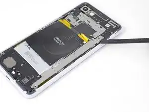
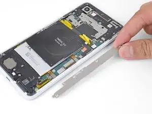
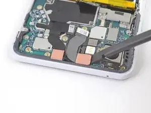
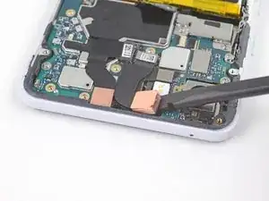
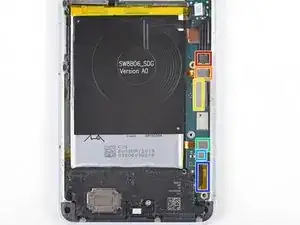
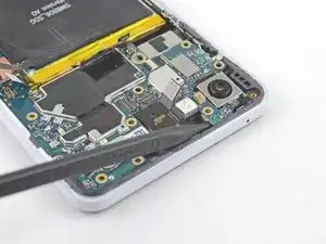
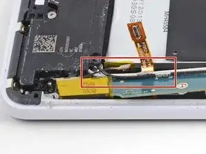
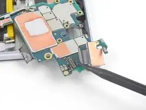
    • Insert the point of a spudger underneath the motherboard, near the rear-facing camera module.

    • Pry up gently to loosen the motherboard from its recess.

    • If the motherboard is not budging, make sure you have disconnected all the connectors.

    • The motherboard has to squeeze past the earpiece speaker cable. If too much pressure is put on the earpiece cable, the earpiece speaker will pop open. You can prevent this by pressing on the earpiece module with a finger while you maneuver the motherboard out.

    • If the earpiece speaker pops open (as shown in the third photo of this step), carefully align and press the module back in place.

  31. 4FacML2Z6XBWjmjX
    4FacML2Z6XBWjmjX
    fHIqg12hndKw16cN
    VxuXYFdPKoTZGBVS
    • Don't attempt to remove the motherboard from the phone. It's still attached to the phone.

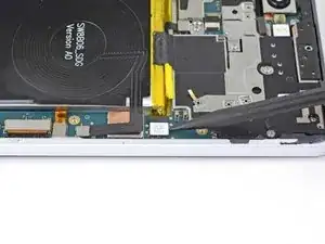
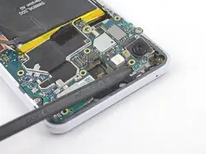
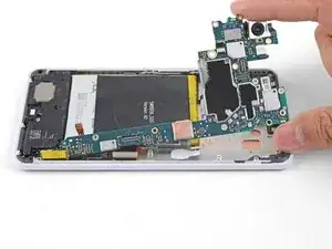
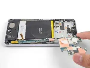
    • While you perform this step, take care to keep slack on the antenna cables attached to the bottom leg of the motherboard.

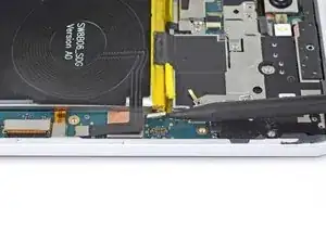
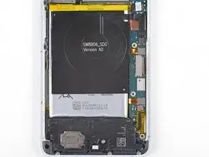
    • Lift the top half of the motherboard slightly to clear the board from its recess.

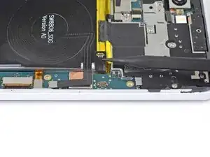
    • Twist the left edge of the board over and out of the phone and rest the board on the right edge of the phone.

  32. MxTBA4JgfhLvXYLa
    MxTBA4JgfhLvXYLa
    BKjaZg3dJAKrBWBP
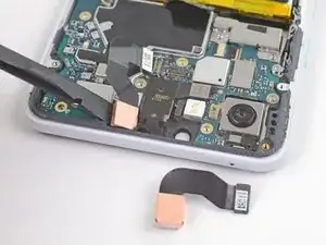
    • Use the point of a spudger to pry up and disconnect the rear-facing camera from its motherboard socket.

  33. bhDIMxdBZPhWbWpb
    • Remove the rear-facing camera.

    • If your replacement camera module has a plastic spacer, be sure to remove it before you install the module.

    • Make sure the lens surface is smudge and dust free before you install the camera assembly.

Conclusione

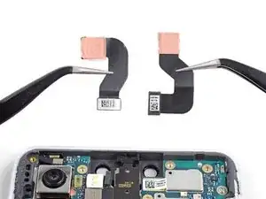
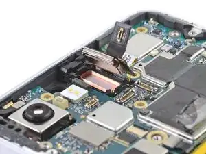
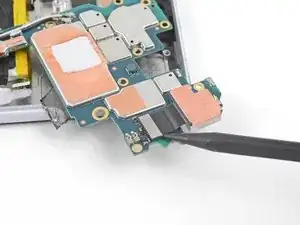
To reassemble your device, follow these instructions in reverse order.

Repair didn’t go as planned? Try some basic troubleshooting, or ask our Answers community for help.

Arthur Shi

Membro da: 03/01/18

248254 Reputazione

0 commenti